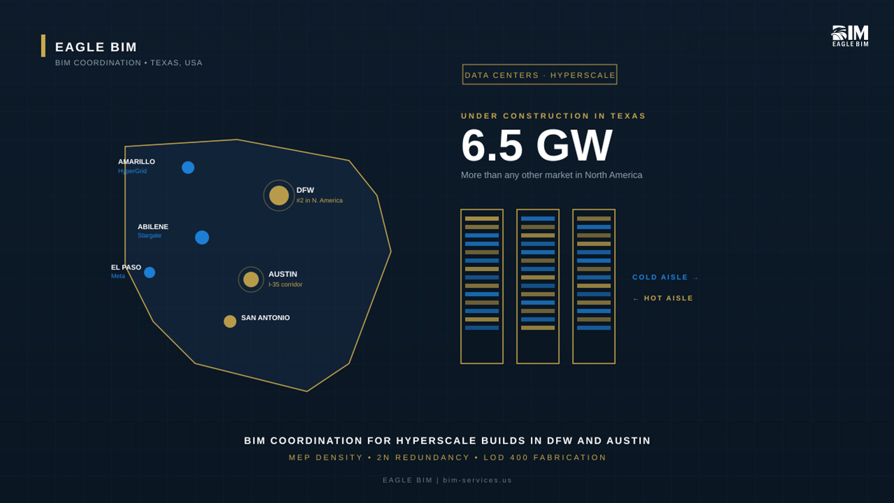
If you’re building a data center in Texas right now, you’re not alone. The state has 6.5 gigawatts of capacity under construction. That’s more than any other market in North America. JLL is projecting Texas to overtake Northern Virginia as the world’s largest data center market by 2030, and the projects driving that growth are big. Vantage’s Frontier campus in Shackelford County. Stargate in Abilene. HyperGrid near Amarillo. Meta’s El Paso build. Amazon’s Bastrop County land grab. Tract’s nearly 3,000-acre campus between Austin and San Antonio. The list keeps growing every quarter.
All of these projects share one thing in common. They cannot be built without BIM for data centers Texas teams running coordination at a level most commercial firms have never touched. The MEP density is on a different planet from a normal office tower. The redundancy requirements double or triple every system. The schedules are aggressive enough that any clash you miss in week three becomes a $200,000 problem in week twenty. This article walks through what makes data center BIM modeling so different, why hyperscalers demand LOD 400 from day one, and what Texas contractors actually need from their BIM partners on these builds.
Whether you’re a GC bidding your first hyperscale shell, an MEP sub trying to figure out if your existing coordination workflow scales, or an owner’s rep asking what to put in the BIM execution plan, this is written for you. Real systems, real coordination challenges, and the specific things that go wrong when teams treat a data hall like a warehouse with extra cooling.
Why Texas Has Become the Second-Largest Data Center Market in the US
The short answer is land, power, and a regulatory environment that says yes faster than anywhere else. The long answer is a combination of forces nobody planned but everybody now benefits from.
Texas has cheap, abundant land outside the major metros. ERCOT is independent of the federal grid, which means power interconnection happens on a different timeline than Virginia or California, where developers are now waiting up to seven years to get connected. Texas tax incentives for data centers are aggressive, and the state’s permitting process is built for speed. Add in the fact that the AI compute boom landed at the same moment Texas was already booming on population and commercial construction, and you get the market we have today.
DFW alone has been running below 4 percent vacancy on data center space for the last two years. The Austin and San Antonio I-35 corridor is filling up just as fast. West Texas around Abilene is suddenly home to OpenAI, Oracle, and Microsoft co-locations. The Panhandle near Amarillo is hosting Fermi America’s HyperGrid. Even El Paso and the border region are seeing 1,000-acre campus deals.
If you want a current map of what’s actually under construction, Data Center Frontier keeps the most reliable running tally. It’s also the best read for understanding where the next wave is headed, because the projects announced today are the ones being coordinated this year.
All of which means the demand for hyperscale MEP coordination in Texas is structurally permanent. This isn’t a 2026 spike. The pipeline runs through 2030 and beyond, and every one of those projects needs a BIM team that understands what hyperscale actually requires. DFW data center construction alone is generating enough work to keep multiple coordination teams busy for years, and the same is true of Austin data center BIM work as the I-35 corridor continues to densify. Mission critical BIM is a different discipline from standard commercial coordination, and Texas is now the place where the most of it happens.
What Makes Data Center BIM Different From Standard Commercial Work
If you’ve coordinated a hospital before, you’re already most of the way there in terms of MEP density. But hospitals look almost simple compared to a hyperscale data hall. Here’s what changes when you step into BIM for data centers Texas work.
System Density and Equipment Clearance
A hyperscale data hall packs more equipment per square foot than almost any other building type. Every rack draws power. Every rack rejects heat. Every rack needs network and storage cabling. Multiply that by hundreds of racks per hall, then add the hot aisle containment, the cold aisle return, the busway above the racks, the cable tray runs, the chilled water piping, and the pre-action sprinkler grid, and you’ve got a coordination problem that does not forgive shortcuts.
Equipment clearance is also a code issue, not just a nice-to-have. NEC 110 sets minimum working clearances around switchgear and panels. NFPA 75 dictates separation requirements for IT equipment. Manufacturer service clearances around CRAC units, UPS modules, and PDUs are typically larger than what designers initially allocate. Data center BIM modeling has to capture every one of these clearances as actual modeled space, not as a note on a drawing somebody might miss. This is one of the most common places where hyperscale MEP coordination work breaks down for teams that haven’t done it before.
2N and 2N Plus 1 Redundancy Modeling
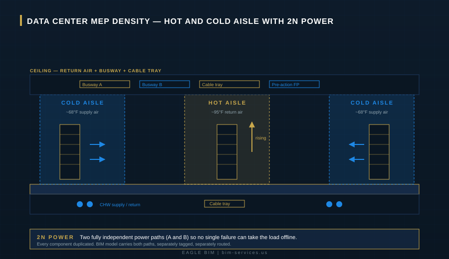
This is the single biggest difference between a data center and any other commercial project. Hyperscalers don’t accept single points of failure anywhere in the power or cooling path. Tier III facilities run N+1 redundancy. Tier IV runs 2N or 2N+1. What that means in practice is that every UPS, every PDU, every chilled water loop, every generator, every switchgear lineup gets duplicated. Two completely independent paths from utility to rack.
In a BIM model, this doubles or triples the work. Path A and Path B have to be physically separated, often in different rooms or different sides of the building, with separate cable trays, separate busways, and separate routing all the way down. Cross-connections happen only at specific transfer points, and even those have to maintain isolation. 2N redundancy modeling is where most BIM teams new to data centers get tripped up. They model the equipment, but they don’t model the separation. That’s how you end up with coordination meetings six weeks in where someone realizes Path A and Path B are sharing a tray, and the whole thing has to be redone.
On a real hyperscale project, 2N redundancy modeling has to extend from the utility yard all the way to the rack. That means substations, switchgear, UPS modules, PDUs, busway, and even the rack-level power supplies are all modeled in pairs with full electrical isolation between them. Hyperscale MEP coordination teams that have done this before track Path A and Path B as separate workshare files within the federated model, which makes it impossible to accidentally route them through shared space.
Hot Aisle and Cold Aisle Coordination
The thermal layout of a data hall is its operating system. Cold air comes up through the raised floor (or down from overhead in newer designs), passes through the racks, and exits as hot return air into the hot aisle. The hot return either rises to a ceiling plenum or gets contained and ducted directly back to the CRAC or CRAH units. None of this works if the BIM model doesn’t accurately capture aisle widths, containment heights, and return path clearances.
Adding to the complexity, AI workloads have changed the rules. Traditional racks ran 5 to 10 kW. AI training racks now routinely hit 100 to 120 kW per rack, which is why you’re seeing every new hyperscale project move to liquid cooling or hybrid air-plus-liquid setups. Liquid cooling adds a whole new layer to the BIM model, with manifolds, leak detection, secondary containment, and serviceability requirements that didn’t exist five years ago.
Raised Floor and Underfloor Routing
Most hyperscale data halls still use raised floors, even where the cold air comes from overhead. The underfloor space is where chilled water piping runs, where power whips travel from the PDU to the rack, where structured cabling sits, and sometimes where leak detection grids live. That’s a lot of utilities competing for limited vertical space.
The BIM model has to capture every penetration through the raised floor for cable cutouts, plus access tile locations, plus structural support points. Get any of this wrong and the field crew finds out at install when the cable whip won’t reach or the chilled water pipe is sitting where a rack support needs to land. Data center BIM modeling at this level is what separates teams that have done five hyperscale projects from teams that have done one.
Common Coordination Challenges on Texas Data Center Projects
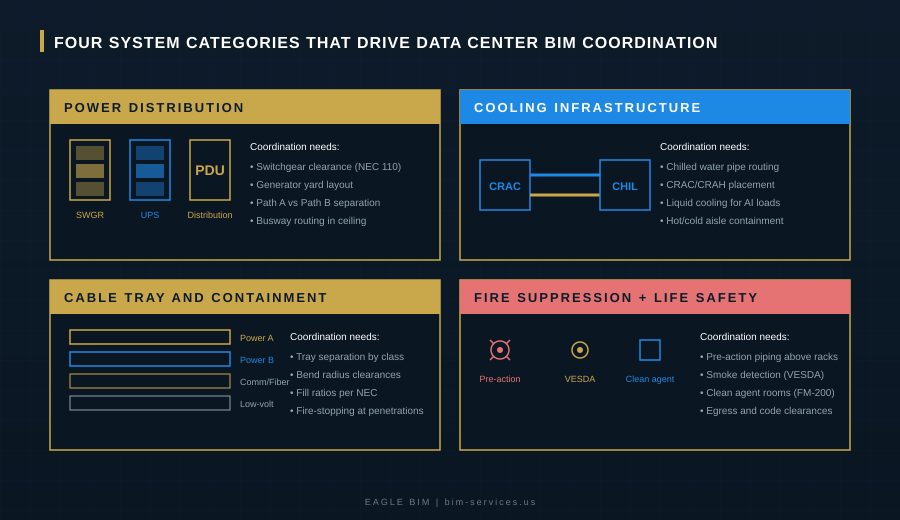
Beyond the systems themselves, Texas adds its own flavor to BIM for data centers Texas work. Climate, grid, water, and code interpretation all play differently here than they do in Virginia or Phoenix. Here are the four system categories that drive most of the coordination work, and what makes them harder in this market. Whether the project is in DFW data center construction territory or in the Austin data center BIM corridor, these four categories show up on every job.
Power Distribution and Switchgear
Texas data centers run on a different power profile than coastal markets. Many hyperscale campuses are now running behind-the-meter generation, which means on-site gas turbines, on-site solar, on-site battery storage, and sometimes nuclear in the longer-term planning. The Microsoft and Chevron deal in West Texas is the most visible example, but it’s far from the only one. What this means for the BIM model is that the utility yard, the substation, the switchgear room, the UPS modules, and the generator yard all have to be coordinated together as a system.
Switchgear lineups in particular need careful clearance modeling. NEC 110.26 working space, manufacturer service clearances, fire-rated separations between transformer and switchgear rooms, and structural support for heavy equipment all stack up. Hyperscale MEP coordination at the power level often involves five different vendors (utility, transformer manufacturer, switchgear manufacturer, UPS manufacturer, PDU manufacturer) and the BIM model is the one place all five sets of equipment data have to coexist.
Cooling Infrastructure (CRAC, CRAH, and Chilled Water)
Texas heat is not a marketing line, it’s a real engineering problem. A hyperscale data center in Dallas in August is rejecting heat into 100-plus-degree ambient air, and the cooling design has to account for that. Closed-loop chiller systems are increasingly the norm because they save water (a real concern given the recent UT Austin report on Texas water consumption from data centers), but they also add complexity to the mechanical room and the rooftop or yard equipment layout.
The BIM model needs to capture every chilled water pipe run from the chiller plant to the CRAC or CRAH units, including expansion loops, valve clusters, and pipe supports rated for the loads involved. Liquid-cooled racks bring a second loop into the building (the technology coolant loop) which adds another piping system entirely. CRAC unit placement, return air paths, and condensate drainage all need clearance and routing modeled to the same standard as the power side.
Cable Tray and Containment
Cable tray work in a data center is its own discipline. Power cabling, communication cabling, fiber, and low-voltage controls all need separated trays, and the separation rules are not casual. Power and comm typically need vertical separation. Path A and Path B power cabling need to stay in separate trays. Fiber needs strict bend radius compliance. Cable fill ratios per NEC limit how much cable can ride in a tray of a given size.
Multiply this by the rack count in a hyperscale hall and you’ve got hundreds of feet of tray, all of which has to coordinate with the busway above the racks, the lighting fixtures, the pre-action sprinkler piping, and the return air ductwork. None of this can be figured out in the field without a fight. Data center BIM modeling has to commit the tray routes early, then hold them through every design revision, because moving a tray run mid-project propagates into every other system. This is one of the things that makes mission critical BIM work fundamentally different from standard commercial coordination.
Fire Suppression and Life Safety
Fire suppression in a data center is unusual. You can’t just put a wet sprinkler system over a hundred million dollars of running servers. Most hyperscale halls run pre-action sprinkler systems, where the pipes are dry until detection signals charge them. Some clean rooms within the building (like network operations centers or battery rooms) use clean agent systems like FM-200 or Novec, which don’t damage equipment when they discharge.
VESDA (very early smoke detection apparatus) systems run in parallel, drawing air samples from above the racks to detect smoke before any sprinkler would activate. All of this hardware lives in the same ceiling space as the busway, the cable tray, the return air, and the structural members. Coordinating fire suppression piping into that space, with proper pitch, hangers, and access for service, is a non-trivial BIM problem. The Uptime Institute’s design guidance on Tier III and Tier IV facilities makes the redundancy expectations explicit, and the BIM model has to deliver on every one of them.
| Building a Data Center in Texas? Eagle BIM Coordinates the Whole Stack.
We model power, cooling, cable, and fire suppression to LOD 400 with full 2N redundancy modeling for hyperscale builds across DFW, Austin, and San Antonio. Texas-based, contractor-facing, ready for OAC meetings on day one. |
Why LOD 400 Is the Standard for Hyperscale Builds
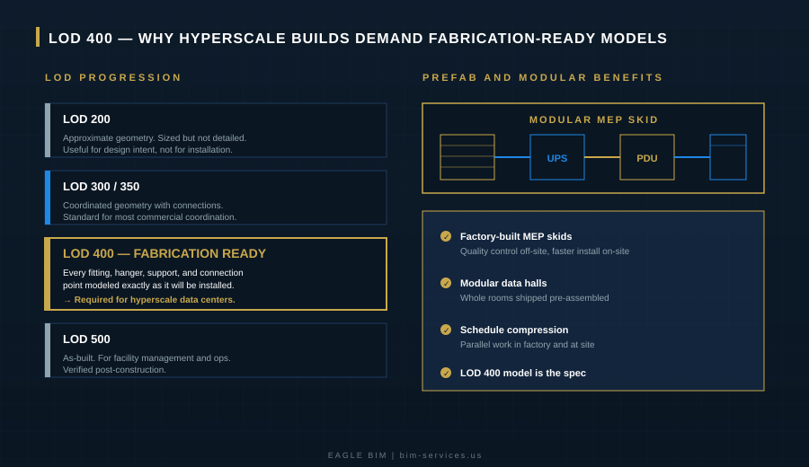
On a typical commercial project, LOD 350 is enough. The model has connections, clearances, and the geometry the field needs to install from. On a hyperscale data center, that’s not enough. Hyperscalers spec LOD 400 from the BIM execution plan stage, and they mean it. BIM for data centers Texas teams that have done this before know to negotiate LOD 400 into the contract from day one, because trying to upgrade mid-project is a mess.
LOD 400 is fabrication-ready. Every fitting is modeled. Every hanger is modeled. Every pipe support, every connection point, every isolation valve, every expansion joint. The model becomes the shop drawing. The MEP sub takes the federated LOD 400 model, sends it to the prefab shop, and the prefab shop builds modules from that geometry directly. There’s no “figure it out in the field” because the field has thirty days to install it and there’s no time for re-engineering.
The other reason LOD 400 matters is that hyperscalers run identical buildings at multiple sites. Meta’s El Paso campus, AWS’s Bastrop campus, and Google’s Midlothian campus are all running standardized data hall designs with minor regional adjustments. The LOD 400 model from one site becomes the starting point for the next. Mission critical BIM at this scale is essentially a kit of parts being deployed against a real estate pipeline. The accuracy of that kit determines how fast each new site can break ground. Austin data center BIM teams working on the Tract Caldwell County campus or the Stargate Milam County site are facing the same kit-of-parts dynamic, with a Texas-specific layer of permitting and utility coordination layered on top.
If your BIM partner is delivering at LOD 350 on a hyperscale spec, you’re going to find out the hard way. Either the prefab shop will reject the model and the MEP sub will eat the cost of the rebuild, or the install crew will hit clashes in the field and the schedule will slip. Neither outcome is good. The fix is to confirm LOD 400 in the proposal, not after the contract is signed.
BIM for Prefabrication and Modular Data Halls
Speed to power is the metric that matters most to hyperscalers in 2026. Every month a building isn’t online is revenue lost, and the AI capacity race has made this brutal. The response from the industry has been to push more and more of the build off-site. Prefabricated MEP skids, modular battery rooms, modular substations, and in some cases entire modular data halls that arrive on trailers and get bolted together at site.
None of this works without BIM for data centers Texas teams operating at LOD 400 from the start. The prefab shop is building from the model. If the model says the UPS module is 84 inches deep and it’s actually 86, the skid won’t fit when it arrives at site. If the busway connection point is modeled half an inch off, the field connection won’t make. Prefab amplifies the cost of any modeling error because the error is built into a physical assembly that has to be re-fabricated. This is where mission critical BIM delivery separates from standard work, because the tolerances are tighter and the consequences of error are larger.
The upside is enormous when it works. Schedule compression of 20 to 30 percent is achievable on the MEP scope, and the quality of factory-built work is consistently higher than field-built. The Vantage Frontier campus near Dallas is leaning heavily into modular construction, and the Stargate Abilene site is reportedly using modular data halls to hit its aggressive timelines. DFW data center construction teams that have built BIM-to-prefab workflows are winning more work because they can hit timelines that traditional approaches cannot.
Eagle BIM’s typical workflow on a prefab-heavy data center starts with a federated LOD 400 model six to eight weeks before the prefab shop needs it. We run shop-drawing-level QC on every module before the model goes to fabrication, then we hold the federated model through install with weekly updates as field conditions get verified. That tight loop is how the schedule actually holds together.
How Eagle BIM Supports Texas Data Center Projects
We’re based in Texas, in association with BIMPRO LLC out of Pflugerville. That puts us inside the Austin and San Antonio corridor by default, with regular travel to DFW for OAC meetings on Dallas-area builds. Our team has done hyperscale MEP coordination on data hall, substation, and modular skid scopes, and we work with GCs, MEP subs, and owner’s reps depending on how the project is structured. DFW data center construction projects and Austin data center BIM engagements both run through the same workflow, with site-specific adjustments for permitting and utility coordination.
Our scope on a typical Texas hyperscale project covers federated model coordination across architectural, structural, mechanical, electrical, plumbing, fire protection, and low-voltage. We deliver to LOD 400 by default for hyperscale work, with full 2N redundancy modeling for power and cooling paths, and we maintain the model through prefab fabrication and field install. Clash detection runs weekly, with formal clash reports going out to all trades before each OAC meeting. Every coordination decision is logged in the model with a date, a discipline owner, and a sign-off. This is what mission critical BIM looks like when it’s done right.
If you want a benchmark for what hyperscale operators actually expect from their BIM partners, the Uptime Institute standards on Tier III and Tier IV facilities are the right starting point. Eagle BIM’s coordination workflow is built to deliver against those standards, with the documentation trail to back it up at handoff.
Beyond BIM for data centers Texas work, our team also handles healthcare, semiconductor, multifamily, and commercial coordination. The data center vertical sits alongside the rest of our work, which means we bring lessons from MEP-heavy hospital projects, fab cleanrooms, and other mission-critical builds into every data center engagement.
The Bottom Line on Data Center BIM in Texas
Texas is the data center build market for the next decade. The pipeline is too deep and too well-funded for that to change. What that means for the BIM industry is that BIM for data centers Texas is no longer a specialty, it’s becoming a baseline expectation for any firm working in this market.
If you’re a contractor or owner about to engage a BIM partner on a hyperscale project, the questions you want to be asking are simple. Does your team understand 2N redundancy at the modeling level? What’s your typical LOD on hyperscale work, and can you show me a recent fabrication-ready model from a similar project? How do you handle the prefab handoff, and how often do your models change after fabrication starts? What’s your clash detection cadence, and how do you document coordination decisions for the owner? Strong data center BIM modeling teams will have answers to all of those questions in writing.
Austin data center BIM teams that can answer those questions in writing are the ones worth working with. The ones who can’t are the reason hyperscalers keep bringing the same handful of firms back project after project. Eagle BIM is positioned to be in that conversation, and the projects coming out of DFW data center construction pipelines, the Austin and San Antonio I-35 corridor, and the West Texas hyperscale corridors are the reason we built our coordination practice the way we did.
| Talk to Eagle BIM About Your Texas Data Center Project
Send us your project scope and we’ll come back with a proposal that addresses 2N redundancy modeling, LOD 400 deliverables, prefab integration, and the specific Texas climate and code considerations that matter on hyperscale builds. No generic templates. No “contact us for pricing” runaround. |