The Corridor Story: Why LOD in BIM Matters More Than Effort
You have a corridor on Level 3. Architecture wants a clean ceiling line. MEP needs hangers and sleeves. Structure guards a beam. Everyone opens the model and starts adding detail “just to be safe.” Two days later, the file is heavier, coordination slows, and the reviewer still asks the same question. The problem is not effort. It is modeling past the LOD in BIM you actually need right now.
For teams working on fast-moving projects across Texas and the USA, over-modeling is one of the quickest ways to lose time, clarity, and approvals. This post keeps it simple: choose the outcome, set the LOD in BIM for this month, and stop where the review can approve.
What LOD in BIM Means (in Plain Words)
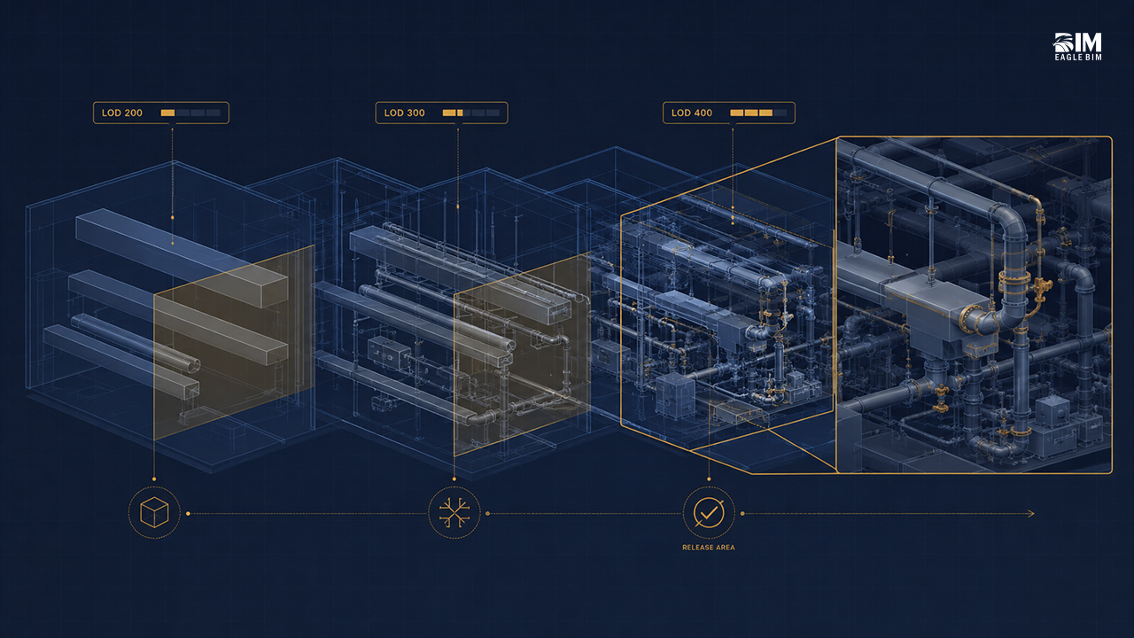
LOD in BIM is not about how detailed your model can be. It is about how detailed it needs to be for the next decision.
-
LOD for design: enough information to approve intent
-
LOD for coordination: enough clarity to avoid conflicts with other trades
-
LOD for fabrication: enough detail for someone to build or install
Pick the outcome for this month. Model to that LOD. Leave the rest for later.
A Quick LOD in BIM Picker You Can Use Right Now
Ask one question before you model anything:
What will this sheet or view be used for in the next meeting?
-
Design signoff:
Model at a design LOD in BIM. Show sizes, locations, and relationships. Skip tiny fittings. -
Trade coordination:
Model at a coordination LOD in BIM. Lock routes, elevations, sleeves, and major supports. -
Fabrication or install:
Model at a fabrication LOD in BIM. Add joints, connections, tags, and tolerances a fabricator can trust.
Put that answer in the meeting agenda so the whole team stops at the same LOD.
The LOD in BIM You Likely Need This Month
Early Design or Schematic LOD in BIM
-
Show rooms, walls, major openings
-
Place main routes and main equipment
-
Use typical sizes
-
Skip brackets, offsets, and boutique geometry
Coordination LOD
-
Lock centerlines and bottom-of-duct/pipe elevations
-
Size and place sleeves on grids
-
Add hangers only where they drive height or clash decisions
-
Cut sections at corridors, risers, and plant rooms
-
Use one consistent elevation rule
Shop or Installation LOD in BIM
-
Add joint types, connection details, and anchors
-
Tie tags directly to schedules
-
Freeze naming so shop drawings inherit the truth
-
Keep only what the field actually needs
Three Simple Rules That Stop Over-Modeling in BIM
-
Model only what you will show on a sheet this month
If it does not support a current decision or approval, leave a note and move on. -
Decide one elevation rule per area
Example: “Main duct centerline on Level 3 targets X ±25 mm.”
One rule prevents endless micro-adjustments. -
Use one view template per drawing type
Consistent views mean faster reviews—and less pressure to over-model to explain yourself.
A Small Plant Room Example (LOD in BIM in Action)
Week 1 goal: prove the main routes work.
We modeled main ducts, pipes, sleeves, and equipment at a coordination LOD in BIM. No valves. No label forest. The gatekeeper call took 30 minutes and approved the layout.
Week 3 goal: release for install.
We added valves, anchors, and connection details only on the runs releasing to fabrication. The rest stayed at coordination LOD in BIM.
Same room. Two outcomes. Two LODs in BIM. Less rework.
What to Include vs What to Skip at Each LOD in BIM
Include Now
-
Sizes and locations that drive approvals
-
Sections through tight spaces
-
Elevations other trades depend on
-
One clear note where a decision is pending
Skip for Later
-
Decorative geometry
-
Every hanger or fitting on long runs
-
Repeated labels
-
Temporary objects you will delete after review
A One-Page LOD in BIM Checklist
Design Signoff
-
Room, wall, and opening layout set
-
Main routes placed and sized
-
Key equipment located with access
-
No tiny fittings or brackets
Coordination
-
Centerlines and elevations locked
-
Sleeves placed on grids
-
Hangers only where they affect height
-
Sections at risers, corridors, plant rooms
-
Elevation rule written in view notes
Shop or Install
-
Joint and connection details added where releasing
-
Anchor points tied to schedules
-
Sheet status correct everywhere
-
Views use the same template
-
File names match sheet numbers and status
If you cannot tick the boxes for the chosen LOD in BIM, the model is trying to do two jobs—and neither will approve quickly.
How to Keep Teams Aligned on LOD in BIM (Texas & USA Projects)
-
Start every coordination call by stating the LOD in BIM for this milestone
-
Put that LOD statement in the agenda and first slide
-
When extra detail appears, ask: “Which sheet is this for next week?”
-
If there’s no answer, park it
We apply the same discipline in Architectural BIM, MEP BIM, and Revit drafting so shop drawings do not inherit noise. This keeps Texas and USA projects lighter, faster, and easier to approve.
Bottom Line
Over-modeling feels productive. It rarely helps the next approval.
Pick the outcome. Pick the LOD in BIM that supports it. Stop where the reviewer can say yes. Your model will load faster. Your meetings will be shorter. Your sheets will pass the first time.
If you want a quick Level of Development pass on your current set, send one sample view and the next milestone date. We will mark what to include now and what to push later so your team can move with confidence.
Frequently Asked Questions
Q1. What does LOD in BIM actually mean?
LOD in BIM (Level of Development) is not about how detailed a model can be — it’s about how detailed it needs to be for the next decision. Design LOD shows enough to approve intent, coordination LOD shows enough to avoid trade conflicts, and fabrication LOD shows enough for someone to build or install. Pick the outcome for this month, model to that LOD in BIM, and stop. Anything beyond the immediate decision is over-modeling that slows reviews without adding value.
Q2. How do I pick the right LOD in BIM for a project phase?
Ask one question before modeling anything: what will this sheet or view be used for in the next meeting? Design signoff needs design LOD in BIM — sizes, locations, and relationships, skip tiny fittings. Trade coordination needs coordination LOD in BIM — locked centerlines, elevations, sleeves, and major supports. Fabrication or install needs fabrication LOD in BIM — joints, connections, tags, and tolerances. Put the answer in the meeting agenda so the whole team stops at the same point.
Q3. What is the biggest cause of over-modeling in BIM projects?
The single biggest cause is teams adding detail ‘just to be safe’ — every hanger, every fitting, every label on a long run modeled before there’s even an agreed elevation rule. The file gets heavier, coordination slows, and the reviewer still asks the same question. The fix is three rules: model only what will appear on a sheet this month, decide one elevation rule per area, and use one view template per drawing type. Over-modeling is a discipline problem, not a tooling problem.
Q4. What LOD in BIM is needed for trade coordination?
For coordination, model main routes with locked centerlines and bottom-of-duct or bottom-of-pipe elevations, place sleeves on grids, add hangers only where they drive height or trigger clash decisions, and cut sections at corridors, risers, and plant rooms. One consistent elevation rule per area (for example, ‘main duct CL on Level 3 targets X ±25 mm’) prevents endless micro-adjustments. Decorative geometry, every fitting, and repeated labels can wait for fabrication LOD in BIM.
Q5. What should be included vs skipped at each LOD in BIM?
Include now: sizes and locations that drive approvals, sections through tight spaces, elevations other trades depend on, and one clear note where a decision is pending. Skip for later: decorative geometry, every hanger on long runs, repeated labels, and temporary objects you’ll delete after review. The discipline is asking ‘does this support the current decision?’ If yes, include. If no, leave a note and move on — that’s what stops over-modeling at every LOD in BIM.
Q6. How does the right LOD in BIM speed up project approvals?
A plant room composite shows it clearly. Week 1 goal: prove main routes work — modeled at coordination LOD in BIM with no valves and no label forest. The gatekeeper call ran 30 minutes and approved the layout. Week 3 goal: release for install — added valves, anchors, and connection details only on runs releasing to fabrication. The rest stayed at coordination LOD. Same room, two outcomes, two LODs, less rework, and faster approvals because the team modeled to the decision in front of them, not the one six weeks away.