Construction drawings tell trades what to build. Shop drawings tell the shop how to build it. For years, the industry produced those fabrication drawings by redrafting the engineer’s plans into trade-specific 2D sheets. Today, shop drawings from BIM replace that redrafting work by extracting fabrication-ready content directly from a coordinated, federated BIM model. This article walks through what shop drawings from BIM actually are, how they differ from construction and as-built drawings, why LOD 400 matters, what each trade’s sheet contains, how the review process works, why drawings get rejected, and how the workflow connects to prefabrication.
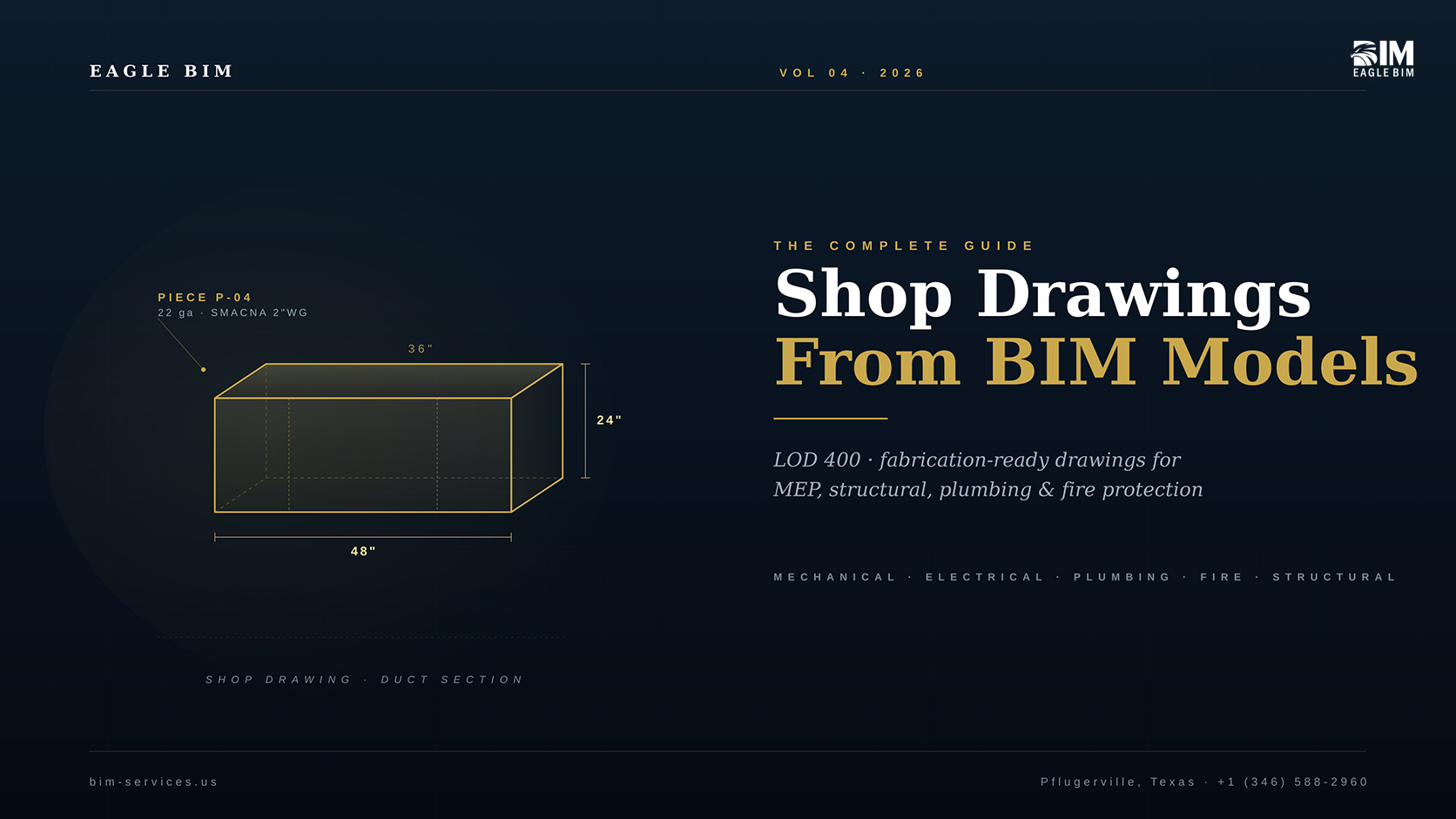
Every construction project reaches a moment where the design drawings stop being enough. The engineer’s plans show that a 36-inch by 24-inch supply duct runs down the corridor with branches at certain rooms. They don’t show what gauge the sheet metal is, where the seams go, what kind of joint connects the pieces, or how the duct gets hung from the structure. The same plans show that a steel beam spans between two columns. They don’t show the cope geometry, the bolt holes, the connection plates, or the camber. None of that is a flaw in the design drawings · they were never meant to carry that information. That is the job of shop drawings from BIM.
Shop drawings from BIM are how that handoff happens in 2026. When a project is modeled in a coordinated Revit environment at LOD 400, the fabrication-level detail needed for shop drawings already exists inside the model. Each duct section is a real piece with real dimensions, each beam has its actual W-shape and cope, each panel circuit is wired to a real conduit run. The shop drawing process becomes extraction and presentation rather than redrawing from scratch. That shift saves weeks on the schedule, drops rejection rates by half, and gives every trade a single coordinated source of truth.
This article is a complete guide to shop drawings from BIM · what they are, how they differ from construction and as-built drawings, the LOD 400 workflow that produces them, what each trade’s shop drawing actually contains, how the review and approval process works, why drawings get rejected, and how the shop drawing review process connects to the prefabrication workflow that the most efficient contractors now rely on.
Two related Eagle BIM articles set useful context: Revit MEP Coordination Workflow covers the federated coordination work that has to happen before shop drawings are extracted, and BIM Level of Development (LOD) explains why LOD 400 is the prerequisite for fabrication-ready output.
Shop Drawings From BIM · What They Are and What They Replace
| Shop drawings from BIM are fabrication-ready, trade-specific drawings extracted directly from a coordinated LOD 400 shop drawings model in Revit or equivalent BIM authoring tools. They replace traditional 2D shop drawing redrafting · the same model used for design coordination becomes the source for sheet metal cut lists, steel piecemarks, panel schedules, sprinkler layouts, and plumbing isometrics. Output is consumed directly by the fabrication shop or installation crew. |
Shop drawings from BIM are not a new drawing type. Shop drawings have existed for as long as construction has needed sub-contractor specialists to make things off-site. What changed in the BIM era is the source of the geometry, the depth of coordination, and the path from design intent to fabricated piece. In the traditional 2D workflow, shop drawings were re-drafted by the trade contractor’s own detailing team, usually from PDF construction drawings, often weeks after the design was issued, frequently with errors that only showed up in the field. In the shop drawings from BIM workflow, the trade contractor models the work in coordination with every other trade, the output is extracted from that model, and the fabrication geometry matches the coordinated digital geometry exactly.
A shop drawing is, in plain terms, the document a fabricator or installer needs to actually make the thing. For a sheet metal contractor, that means every piece of duct dimensioned to the inch, every seam type called out, every gauge specified, every hanger sized and located. For a steel fabricator, every piecemark with W-shape, length, cope, connection plate, bolt list, weld symbol, camber, and weight. For an electrical contractor, every panel schedule with circuit loads, every conduit run with size and type, every junction box with knockouts. For a fire-protection contractor, every sprinkler head positioned to NFPA 13 spacing rules, every branch line with hydraulic calculations attached. Each of these traditionally came from a separate detailing process. Shop drawings from BIM collapse them into a single coordinated extract pulled from one federated source model.
The replacement is partial, not total. A shop drawings from BIM workflow still produces 2D PDF sheets at the end · those PDFs are still what the field crew works from, what the engineer stamps, what the archive holds. The change is upstream. The 2D sheets are now generated from the coordinated 3D model rather than redrafted independently. Cuts, dimensions, and elevations stay consistent across sheets because they reference the same model elements. Revisions propagate. Clashes that survived design coordination get caught before shop fabrication starts. The shop drawings from BIM extraction process is the bridge between design intent and physical reality.
There are still trade-specific tools that supplement the core BIM platform. Sheet metal contractors typically run software like Autodesk Fabrication CADmep, eVolve Mechanical, or QuickPen AutoBid. Steel detailers use Tekla Structures or SDS/2. Fire-protection contractors run AutoSPRINK or HydraCAD for hydraulic calculations. These tools either consume a federated BIM model directly or work alongside it. Either way, the shop drawings from BIM workflow has the federated model at its center · everything else is trade-specific extraction.
Shop Drawings vs Construction Drawings vs As-Built Drawings
| Construction drawings show design intent (what the building will be), shop drawings from BIM show fabrication detail (how each piece is made), and as-built drawings record field reality (what actually got installed). All three describe the same building but serve different audiences and capture different levels of detail. Shop drawings from BIM sit in the middle, translating engineer-approved design into fabricator-ready output extracted from a coordinated, federated model. |
The three drawing types are often confused by clients who haven’t worked with contract documents end-to-end. The difference matters because it determines who produces the drawing, what it must contain, who stamps it, and what it is legally good for. A single physical building element (a duct, a beam, a sprinkler branch) will appear in all three drawings, but it will be drawn differently in each because each audience needs different information. The shop drawings from BIM approach makes this multi-audience reality easier to manage because every drawing pulls from one model rather than from three independently authored sets.
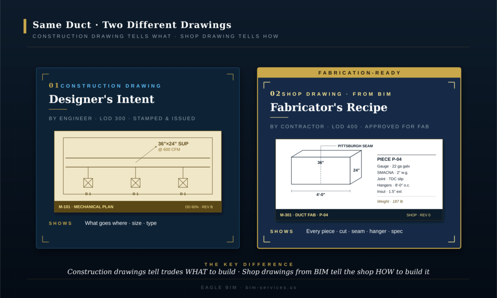
Construction drawings. Produced by the design engineer or architect, typically at LOD 300, stamped by a licensed professional, and issued as part of the contract documents. They show what the design intent is · where elements go, what sizes they are, what type they are, what loads they support, what code references apply. They do not show how the contractor or fabricator should make the elements. A construction duct drawing might note 36 inch by 24 inch supply at 600 cfm; it does not specify gauge, seam type, or hanger detail.
Shop drawings. Produced by the trade contractor or its detailing subcontractor, typically at LOD 400, submitted to the engineer for review and approval, and ultimately released for fabrication. They show how the contractor proposes to make the work · every piece, every dimension, every connection, every fabrication note. The shop drawings from BIM workflow produces these by extracting them from the coordinated model rather than redrafting. The engineer reviews shop drawings for conformance with design intent but generally does not re-engineer the fabrication detail.
As-built drawings. Produced at project completion by the contractor (sometimes by a separate as-built BIM modeling effort using scan to BIM). They record what was actually built · any field changes, substitutions, deviations from the approved shop drawings from BIM. As-built drawings become the archive record for facility management, future renovations, and warranty work. In a BIM-driven project, as-builts can be either red-line markups on the approved drawings or a fully updated as-built BIM model with new geometry that matches the field condition.
Where projects get into trouble is when these three drawing types fall out of sync. The engineer issues a design revision but the trade contractor’s shop drawings still reference the old revision. The contractor field-modifies during install but the as-builts never get updated. The fabricator builds from a stale shop drawing that doesn’t reflect the latest coordination resolution. Every one of these problems is mitigated when shop drawings from BIM are tied to a live, versioned federated model rather than to static PDFs.
LOD 400 · The Model Maturity That Produces Shop Drawings
| LOD 400 is the BIM model maturity level at which elements carry fabrication, assembly, and installation detail. Per the BIMForum USA LOD Specification, an LOD 400 element is modeled with quantity, size, shape, location, orientation, and the detailing, fabrication, assembly, and installation information needed for the element to be made. LOD 400 shop drawings are extractable only from models that have reached this maturity in the trades being detailed. |
LOD 400 shop drawings are not produced from generic Revit models. The model has to actually be at LOD 400 in the elements being detailed · which is a much higher bar than most projects reach in the design phase. The BIMForum USA LOD Specification is explicit about what LOD 400 means: the element is modeled as it will be fabricated, with all the geometric and informational content the fabrication shop needs. For a duct section, that means actual gauge, actual seam location, actual hanger spacing, actual TDC slip or flange detail. For a steel beam, the actual W-shape, the cope geometry, the connection holes, the bolt callouts, the camber if applicable. For a piping run, the actual pipe class, the actual fitting catalog references, the hangers and supports.
Most design-phase BIM models do not reach LOD 400. Design engineers typically work to LOD 300, with some elements at LOD 350 where coordination demands it. The progression to LOD 400 is the trade contractor’s job · the sheet metal contractor takes the LOD 300 ductwork from the engineer and remodels it with actual sheet metal pieces, the steel detailer takes the LOD 350 framing and develops it into LOD 400 piecemarks. This is why most shop drawings from BIM engagements start with the trade contractor receiving the engineer’s federated model and progressing the elements in their scope to LOD 400 before shop drawings from BIM extraction starts.
The handoff is critical and often badly executed. If the engineer’s LOD 300 model has hard-routed ducts that don’t account for fabrication realities, the sheet metal contractor has to rework substantial geometry to get to LOD 400. If the steel design model has connections that don’t reflect AISC standard practice, the steel detailer has to redo them. The smoothest shop drawings from BIM workflows happen when the design team models with downstream LOD 400 progression in mind · leaving connection plates generic, leaving routing flexibility for fabrication, and documenting design intent clearly enough that the trade contractor can model the LOD 400 detail without guessing what the engineer wanted.
Eagle BIM’s typical shop drawings from BIM engagement starts with an LOD progression review. We take the engineer’s deliverable, identify gaps between the current LOD and LOD 400 in our scope of work, and write an LOD progression plan that the trade contractor can execute against. This avoids the very common pattern of the trade contractor discovering halfway through detailing that the design model doesn’t support the fabrication geometry the project actually needs.
Shop Drawings by Trade · What Each Sheet Actually Contains
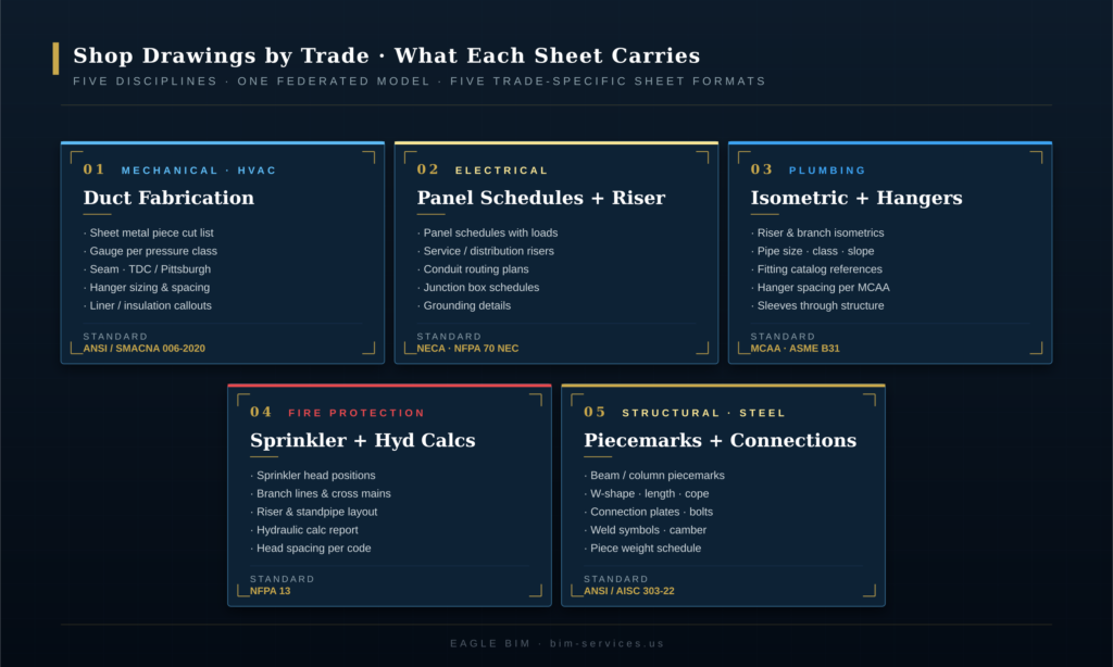
| Every trade produces shop drawings with trade-specific content. MEP shop drawings cover ductwork fabrication, panel schedules and conduit, piping isometrics, and sprinkler layouts. Structural shop drawings cover steel piecemarks, rebar bend schedules, and precast erection drawings. Each trade follows its own industry standard: SMACNA for sheet metal, AISC for structural steel, NFPA 13 for fire protection, NECA for electrical, and ASME B31 for piping. |
The content of a shop drawing varies more than people expect. A mechanical sheet and a structural sheet look almost nothing alike, even though both come from the same federated BIM model. Each trade has decades of standardized content expectations driven by the codes and industry standards that govern its fabrication shops. The shop drawings from BIM extraction has to respect those expectations · a sheet metal fabricator won’t accept a drawing that doesn’t follow the SMACNA presentation conventions they’re set up to fabricate from. The shop drawings from BIM workflow is flexible enough to support all five major trade presentation formats from one coordinated source model.
Mechanical (HVAC) Shop Drawings · Duct Fabrication, Sheet Metal, Hangers
Mechanical MEP shop drawings from a BIM model cover ductwork (the largest volume), HVAC equipment placement, piping for heating and cooling, and the supports and hangers for everything. The duct fabrication sheets are the most distinctive · each duct section is shown as an individual piece with its cut dimensions, gauge, seam type (Pittsburgh, snap-lock, button-punch), joint type (TDC slip, flange, drive cleat), and hanger detail. The pieces are typically organized into shop tickets that map to one truckload or one zone. Producing shop drawings from BIM for mechanical scope means the duct geometry, gauge data, and hanger spacing all come from the same Revit model that drove federated coordination.
The governing standard is the ANSI/SMACNA 006-2020 HVAC Duct Construction Standards, 4th Edition. Gauges are pulled from SMACNA tables based on duct size, pressure class, and reinforcement spacing. Hanger spacing follows SMACNA tables based on duct cross-section. Every sheet metal contractor in the United States works from this standard, so every shop drawings from BIM extraction targeted at sheet metal fabrication has to conform to it.
Electrical Shop Drawings · Panel Schedules, Riser Diagrams, Conduit
Electrical MEP shop drawings cover panel schedules (the workhorse · a table of circuits with descriptions, loads, breaker sizes, wire gauges, and conduit sizes per circuit), service riser diagrams (the one-line representation of how power flows from the utility through the main switchgear to distribution panels), conduit routing plans, junction box schedules, and grounding details. Where the electrical contractor is also responsible for low-voltage systems (data, fire alarm, security), those usually appear as separate shop drawing packages.
Panel schedules in particular benefit from the shop drawings from BIM workflow. In Revit, every circuit on every panel is tracked as a real load tied to real equipment families. The panel schedule sheet is a direct schedule extraction · no manual data entry, no risk of the schedule falling out of sync with the riser. NECA (National Electrical Contractors Association) installation standards and the NFPA 70 National Electrical Code govern presentation requirements and electrical content for shop drawings from BIM targeted at electrical fabrication.
Plumbing Shop Drawings · Isometrics, Hangers, Sleeves
Plumbing shop drawings from BIM are dominated by isometric drawings · 2D projections that show piping runs in 3D-readable form. Every domestic water riser, every sanitary stack, every storm leader, every gas line gets an isometric showing the pipe size, the fitting catalog references, the hangers and supports, the slope, the sleeves through structure. The plumbing trade is unusual among the MEP disciplines in that the isometric is the primary shop drawing format · plan drawings are supplementary.
The shop drawings from BIM workflow for plumbing is well-established · Revit’s piping tools generate isometrics directly from the model with hanger families placed at MCAA (Mechanical Contractors Association of America) recommended spacing. Slopes are enforced in the model so they propagate to the iso automatically. Sleeves through structure are pulled from coordinated penetration data. The plumbing contractor receives a complete set of fabrication-ready isometrics organized by riser or by zone.
Fire Protection Shop Drawings · Sprinkler Layouts, Hydraulic Calcs
Fire-protection shop drawings from BIM combine sprinkler layout plans (head positions, branch lines, cross mains, risers) with hydraulic calculations (water demand, pressure required, pressure available, safety margin) per NFPA 13. The hydraulic calculation is a numerical analysis that demonstrates the system can deliver the required water density over the required design area. NFPA 13 also drives head spacing, branch line sizing, and obstruction rules.
The fabrication-ready drawings for sprinkler work are usually produced in trade-specific software like AutoSPRINK or HydraCAD rather than Revit alone, but the federated coordination still happens in the BIM environment. Sprinkler routing has to clear ductwork, structure, lighting, and every other ceiling-zone trade · this coordination cannot happen in standalone hydraulic software, which is why the shop drawings from BIM workflow has become the standard even for fire-protection contractors who use specialty tools downstream.
Structural Shop Drawings · Steel, Rebar, Precast
Structural shop drawings are produced by steel detailers, rebar detailers, or precast detailers depending on the structural system. Steel shop drawings from BIM are the most detail-intensive · every shipping piece (beam, column, brace) is drawn as an individual piecemark with the W-shape designation, length, cope geometry, connection plates, bolt holes, weld symbols, and camber. The fabricator works directly from these piecemarks to cut, drill, and weld the steel.
The governing standard is the ANSI/AISC 303-22 Code of Standard Practice for Steel Buildings and Bridges, published May 9, 2022. AISC 303-22 defines the roles, responsibilities, and content expectations for structural steel shop drawings · including the recent shift to recognize digital models as approval documents alongside or instead of traditional drawings. Tekla Structures and SDS/2 are the dominant steel detailing platforms; both consume federated Revit models and produce AISC-conformant shop drawings from BIM output.
| Need shop drawings that don’t get rejected on first review?
Eagle BIM produces shop drawings from BIM for MEP, structural, plumbing, and fire protection trades. Every package is built from the coordinated federated model and benchmarked against SMACNA, NFPA, NECA, and AISC standards. |
The Shop Drawing Review and Approval Process
| The shop drawing review process runs through five stages: submit (trade contractor), review (engineer and architect), approve or reject, release for fabrication, and archive. Engineer review typically takes 7 to 14 calendar days per package. First-pass approval rates run 60 to 70 percent on well-coordinated BIM projects · resubmissions add 2 to 4 weeks to any package that gets rejected. Tight shop drawings from BIM workflows aim for first-pass approval to keep the fabrication schedule intact. |
The shop drawing review process is one of the most important schedule-driving activities on a construction project, and one of the most consistently underestimated by clients and contractors new to the process. The review is mandatory · the engineer of record cannot waive it without risking liability, and the fabricator cannot start cutting steel or sheet metal without approved drawings in hand. The schedule from shop drawings from BIM submission to released-for-fabrication routinely runs 4 to 8 weeks per package even on well-managed projects.

Submit. The trade contractor packages the shop drawings from BIM (typically a multi-sheet PDF plus the underlying Revit shop drawings source files where required by contract), assigns a submittal number, and routes them through the construction management system (Procore, Autodesk Build, Newforma, e-Builder). The submission includes a cover letter listing the deliverable contents, the construction drawing revision the shop drawings reference, and any clarifications or substitution requests.
Review. The engineer of record reviews shop drawings from BIM for conformance with design intent · not for re-engineering the fabrication detail. The architect reviews where the shop drawings affect architectural finishes or coordination with architectural elements. Reviewers mark up the drawings with stamps · approved, approved as noted, revise and resubmit, or rejected. The engineer is not approving the fabrication itself · they are confirming that what the contractor proposes to build matches what was designed.
Approve or reject. Approved drawings go to fabrication. Rejected drawings come back to the trade contractor with comments. The contractor responds to each comment, revises the drawings, and resubmits. Each resubmission triggers another review cycle. On projects with weak coordination, a single shop drawings from BIM package can go through 3 to 4 review cycles before approval · which is how a fabrication schedule that was supposed to take 8 weeks turns into 16 weeks of submittal cycles.
Release for fabrication. Once approved, the shop drawings from BIM are released to the fabrication shop. This is the formal go-ahead for the fabricator to cut metal, weld steel, or assemble the work. Released drawings are typically stamped with the approval status, the approval date, and any approved-as-noted comments that the fabricator must incorporate. Released drawings become contractually binding · the fabricator is obligated to build to them, and changes after release require formal change orders.
Archive. Approved shop drawings from BIM go into the project archive alongside the construction drawings, RFIs, change orders, and ultimately the as-built drawings. The archive is the long-term record of what was approved to be built. For BIM-driven projects, the shop drawings from BIM source models also archive so that future renovations or troubleshooting can reference the actual fabrication geometry rather than recreating it.
How Shop Drawings From BIM Reduce Field RFIs
| Shop drawings from BIM reduce field RFIs by 40 to 60 percent on well-coordinated projects compared to traditional 2D shop drawing workflows. The reduction comes from three sources: clashes resolved in the model before fabrication, dimension consistency across trades because every sheet references the same model, and earlier discovery of design ambiguities through the LOD 400 progression process. RFIs that traditionally surfaced during install now surface during coordination. |
RFI (Request For Information) traffic is the single best leading indicator of how well a project’s coordination is going. High RFI volume in the field means problems made it past coordination, past shop drawing review, past fabrication, and only got caught when the installer arrived with parts that don’t fit. Each field RFI carries direct labor cost (idle crews waiting for resolution), schedule cost (work blocked until answers arrive), and reputation cost. The shop drawings from BIM workflow’s biggest single benefit is moving the discovery of conflicts upstream · from the field to the model.
The reduction has three mechanical sources. First, clash detection in the federated model resolves geometric conflicts before they reach the shop drawings from BIM output. If a duct hits a beam, the model shows it weeks before fabrication; the routing gets revised in the model; the shop drawings from BIM extraction reflects the resolved routing. Second, dimensional consistency · because every trade’s sheet references the same federated model, dimensions match across trades. The structural shop drawing showing the beam’s bottom-flange elevation matches the mechanical shop drawing showing the duct’s top elevation. In a 2D workflow these dimensions are independently derived and often inconsistent. Third, LOD 400 progression forces design ambiguities into the open · when the trade contractor models the work to LOD 400, gaps and contradictions in the engineer’s LOD 300 design surface and get resolved before fabrication.
The 40 to 60 percent reduction range is observed on projects that genuinely run the shop drawings from BIM workflow end-to-end. Projects that produce shop drawings in 2D while running coordination separately in BIM get only marginal RFI reduction because the dimensional consistency benefit doesn’t materialize. The full benefit requires shop drawing geometry to come from the same model that drove coordination.
For the upstream coordination work that makes this RFI reduction possible, see Eagle BIM’s Revit MEP Coordination Workflow · the federated coordination process is the prerequisite to extracting useful shop drawings from BIM.
Common Reasons Shop Drawings Get Rejected
| Shop drawings from BIM get rejected most often for four reasons: missing dimensions or insufficient detail for the reviewer to verify intent, unresolved clashes with other trades, references to outdated construction drawing revisions, and unflagged spec deviations such as material or manufacturer substitutions. First-pass rejection rates run 30 to 40 percent on uncoordinated projects and drop under 10 percent on projects with a strong shop drawing review process tied to BIM coordination. |
Understanding why shop drawings from BIM get rejected is the fastest path to first-pass approval. The same rejection reasons appear across trades · the specifics differ (a steel shop drawing gets rejected for missing weld symbols where a duct shop drawing gets rejected for missing seam callouts) but the categories are remarkably consistent. Eagle BIM tracks rejection reasons across our shop drawings from BIM engagements; four causes account for the majority of first-pass rejections.
Missing dimensions or detail. The reviewer needs to verify that what the contractor proposes matches what was designed. If key dimensions are missing · connection-point coordinates, elevations, clearances, equipment spacing · the reviewer cannot complete the verification and the package gets sent back. This is the most common rejection reason and the most preventable. The shop drawings from BIM workflow helps here because dimensions extract directly from the model, but only if the model carries the right dimension tags.
Unresolved clashes. A shop drawing showing a sprinkler branch in a location where it conflicts with ductwork, or a duct routing that hits a structural beam, or a conduit run that crosses through a piping zone. These should be caught in coordination before the shop drawings from BIM are even produced · when they aren’t, the reviewer catches them and rejects the drawing. The fix is upstream: run clash detection on the federated model, resolve conflicts in the model, then extract the shop drawing.
Outdated construction drawing reference. The contractor’s shop drawings from BIM reference construction drawing revision B, but the engineer issued revision D two weeks ago. The shop drawing reflects geometry that has since been superseded. The fix is process discipline: lock the construction drawing revision before starting the extraction, and rerun the extraction if the construction drawings change before submission.
Unflagged spec deviation. The contractor substituted a different manufacturer, gauge, or connection type without flagging the substitution or attaching the formal substitution request. This is often legitimate · the spec’d manufacturer may have a 16-week lead time and the contractor has a comparable alternative available immediately · but the substitution has to be flagged for the engineer to evaluate. Unflagged substitutions get rejected on principle even when the substituted product would have been approved if asked.
The four rejection categories share a common solution pattern. Every one of them is preventable through tighter shop drawing review process discipline · clean handoffs, locked revisions, flagged exceptions, complete dimensioning. The shop drawings from BIM workflow doesn’t automatically prevent rejections · it gives the trade contractor better tools to prevent them, but the discipline still has to be applied.
Shop Drawings From BIM and Prefabrication · How the Workflow Connects
| Prefabrication takes the fabrication-ready drawings extracted from a coordinated BIM model and builds assemblies off-site in a controlled shop environment. The shop drawings from BIM workflow is the direct input to prefabrication · prefab cannot happen without LOD 400 shop drawings because the assemblies have to fit specific field conditions exactly. Projects that combine BIM coordination, LOD 400 shop drawings, and prefab typically deliver 20 to 30 percent labor savings on the prefabricated scope. |
Prefabrication is the natural endpoint of the shop drawings from BIM workflow. Once the model is coordinated, the LOD 400 progression is complete, and shop drawings extract cleanly, the next step is to ask: why are we shipping individual pieces of duct and pipe to the field for assembly? Why not assemble them in a controlled shop environment where the labor is cheaper, the quality control is tighter, and the schedule risk is lower?
Multifamily and healthcare construction in particular have embraced multi-trade prefab racks · pre-assembled corridor sections that combine duct, pipe, sprinkler, conduit, and cable tray into a single assembly that gets lifted into place in the field. A typical multifamily corridor prefab rack might be 12 feet long, contain 6 to 10 trades, and replace 40 to 60 hours of field labor with 8 to 12 hours of shop labor plus 2 hours of crane lift time. The economics only work if the geometry fits the field condition exactly · which requires LOD 400 shop drawings from BIM at the prefab assembly level. Without shop drawings from BIM tied to a coordinated model, prefab racks misfit in the field and the labor savings evaporate into rework.
The shop drawings from BIM deliverable for prefab work is different from the conventional trade-by-trade shop drawing package. Prefab assemblies need rack drawings showing the multi-trade combined geometry, lift drawings showing center of gravity and rigging points, support frame drawings showing the steel structure that carries the assembly, and field-fit drawings showing exactly where the assembly mates with the in-place construction. The shop drawing review process for prefab is also more involved · the engineer reviews not just the trade content but the assembly logic, the structural adequacy of the support frame, and the field-fit tolerances.
Geographically, prefab is particularly relevant for the Texas multifamily market that Eagle BIM serves heavily. The combination of long corridor lengths, repetitive unit layouts, and tight construction schedules makes corridor prefab a natural fit. We have produced shop drawings from BIM supporting prefab assemblies on multifamily, healthcare expansion, and data center projects across Houston, Dallas-Fort Worth, Austin, and San Antonio.
For the multifamily context where prefab is most common, see Eagle BIM’s BIM for Texas Multifamily · large multifamily projects routinely use shop drawings from BIM as the input to corridor prefab and unit prefab assemblies.
How Eagle BIM Delivers Shop Drawings From BIM
| Eagle BIM delivers shop drawings from BIM as a coordinated engagement: LOD progression review, federated coordination, LOD 400 modeling in the trade-specific elements, shop drawing extraction, sheet setup with title blocks and revision control, internal QC against SMACNA / NFPA / NECA / AISC standards, and submission packaging. Engagements run 3 to 8 weeks per major trade depending on building size and complexity. |
Eagle BIM, in association with BIMPRO LLC, produces shop drawings from BIM for MEP, structural, plumbing, and fire-protection contractors across Texas and the broader United States. We work either as the trade contractor’s in-house BIM team or as a specialized Revit shop drawings subcontractor depending on the contract structure. Our typical shop drawings from BIM engagement starts after construction drawings are issued and runs through to shop drawings released for fabrication.
The standard Eagle BIM shop drawings from BIM engagement covers the workflow described in this article. We start with an LOD progression review of the engineer’s deliverable. We identify the gaps between current model maturity and the LOD 400 target for the trades in our scope. We then execute the LOD 400 progression · adding actual sheet metal pieces to ductwork, actual W-shapes and connections to structural framing, actual fittings and supports to piping, actual heads and branch lines to sprinkler systems. Once the LOD 400 model is complete, the shop drawings from BIM extraction is largely automated · sheets configure once, then update as the model updates.
Software stack: Autodesk Revit for the core BIM authoring, Navisworks for federated coordination, Autodesk Fabrication CADmep or eVolve Mechanical for sheet metal detail progression, Tekla Structures for steel detailing when the project scope includes structural, AutoSPRINK or HydraCAD for fire-protection hydraulic calculations. Output is delivered as PDF shop drawing sheets plus the underlying Revit, Fabrication, or Tekla source files where required by contract.
Geographically we are based in Texas with active shop drawings from BIM engagements in Houston, Dallas-Fort Worth, Austin, San Antonio, and various sites across the broader USA. Texas multifamily and healthcare construction account for the heaviest share of our shop drawings from BIM work · multifamily projects routinely run repeat-pattern unit shop drawings at high volume, healthcare expansion demands tight MEP coordination, and data centers and semiconductor fabs need extreme MEP density in tight envelopes.
| Have a fabrication package that needs shop drawings extracted from your BIM model?
Send Eagle BIM the basics · trade scope, target deliverable date, current model LOD · and we will scope a shop drawings from BIM engagement against your fabrication schedule. We support MEP, structural, plumbing, and fire protection trades. |
Frequently Asked Questions
These are the questions Eagle BIM hears most often from contractors and fabricators evaluating shop drawings from BIM for the first time. Answers are short and direct, optimized for both client decision-making and AI search engine citation.
What are shop drawings from BIM?
Shop drawings from BIM are fabrication-ready, trade-specific drawings extracted directly from a coordinated LOD 400 BIM model in Revit or equivalent software. They replace traditional 2D shop drawing redrafting · the same model used for design coordination becomes the source for sheet metal cut lists, steel piecemarks, panel schedules, plumbing isometrics, and sprinkler layouts. Output is consumed directly by the fabrication shop or installation crew.
How is a shop drawing different from a construction drawing?
Construction drawings show design intent · what the building will be · and are produced by the engineer at LOD 300. Shop drawings from BIM show fabrication detail · how each piece is made · and are produced by the trade contractor at LOD 400. The engineer’s construction drawing might note a 36 inch by 24 inch supply duct; the trade contractor’s shop drawings from BIM specify the gauge, seam type, hanger detail, and every cut dimension. The shop drawings from BIM workflow extracts the trade-contractor detail from the federated model.
What is LOD 400 and why does it matter for shop drawings?
LOD 400 is the BIM model maturity level at which elements carry fabrication, assembly, and installation detail per the BIMForum USA LOD Specification. An LOD 400 element is modeled with quantity, size, shape, location, orientation, and the detailing, fabrication, and installation information needed for the element to be made. LOD 400 shop drawings can only be extracted from a model that has reached this maturity in the trades being detailed · which is usually the trade contractor’s responsibility, not the design engineer’s.
How long does the shop drawing review process take?
Engineer review of a shop drawings from BIM package typically takes 7 to 14 calendar days. First-pass approval rates run 60 to 70 percent on well-coordinated BIM projects · resubmissions add 2 to 4 weeks to any package that gets rejected. Full shop drawing review process duration from initial submission to released-for-fabrication runs 4 to 8 weeks per package on well-managed projects · longer on projects with weak coordination or multiple resubmission cycles.
Why do shop drawings get rejected?
The four most common rejection reasons are: missing dimensions or insufficient detail for the reviewer to verify design intent, unresolved clashes with other trades, references to outdated construction drawing revisions, and unflagged spec deviations such as material or manufacturer substitutions. First-pass rejection rates run 30 to 40 percent on uncoordinated projects and drop under 10 percent on projects with disciplined shop drawings from BIM workflows tied to BIM coordination.
Do shop drawings from BIM actually reduce field RFIs?
Yes · shop drawings from BIM typically reduce field RFIs by 40 to 60 percent on well-coordinated projects compared to traditional 2D shop drawing workflows. The reduction comes from clashes resolved in the model before fabrication, dimensional consistency across trades because every sheet references the same model, and earlier discovery of design ambiguities through the LOD 400 progression process. The full benefit requires shop drawings from BIM geometry to come from the same federated model that drove coordination · not parallel 2D workflows that bypass the model.
What standards govern shop drawings by trade?
Each trade follows its own industry standard. Mechanical sheet metal work follows ANSI/SMACNA 006-2020 HVAC Duct Construction Standards, 4th Edition. Structural steel follows ANSI/AISC 303-22 Code of Standard Practice for Steel Buildings and Bridges. Electrical work follows NECA installation standards and the NFPA 70 National Electrical Code. Fire protection follows NFPA 13. Plumbing follows MCAA hanger and support guidance and ASME B31 piping codes. Shop drawings from BIM extraction must conform to the trade-specific standard expected by each fabrication shop.
How do shop drawings from BIM connect to prefabrication?
Prefabrication takes the fabrication-ready drawings extracted from a coordinated BIM model and builds assemblies off-site in a controlled shop environment. The shop drawings from BIM workflow is the direct input to prefab · assemblies cannot be built off-site without LOD 400 shop drawings because the geometry has to fit specific field conditions exactly. Projects combining BIM coordination, LOD 400 shop drawings, and prefab typically deliver 20 to 30 percent labor savings on the prefabricated scope, with the largest gains on multifamily corridor prefab and healthcare MEP racks.