
Most projects don’t fail because the design was wrong. They fail because the gap between design intent and shop-drawing-ready never closes cleanly, and by the time the field crew opens the model, half the routing won’t fit and the other half conflicts with structural. That gap is where every MEP project either gains a decisive advantage or quietly accumulates rework. A good Revit MEP coordination workflow closes that gap deliberately. Bad coordination leaves it open and lets the field figure it out.
This blog walks through Eagle BIM’s eight-week Revit MEP coordination workflow from initial design model intake to a coordinated LOD 400 fabrication-ready release. It is the actual cadence we run on commercial, healthcare, data center, and fab projects across Texas. We use it because it works. Eight weeks gives a coordination team enough room to validate models, run multiple clash cycles, advance LOD, and hand fabricators a release they can actually build from. Shorter than that and quality slips. Longer than that and the project schedule starts paying for it. Eight weeks is the number we land on after running this on dozens of jobs.
If you’re a general contractor scoping MEP BIM services for an upcoming build, this is what good looks like. If you’re a project manager trying to evaluate whether your current BIM partner is actually delivering or just running the meter, this is the standard to measure them against. And if you’re a designer or owner trying to write a BIM execution plan that actually produces buildable output, this is the framework that gets you there.
What the Revit MEP Coordination Workflow Actually Does
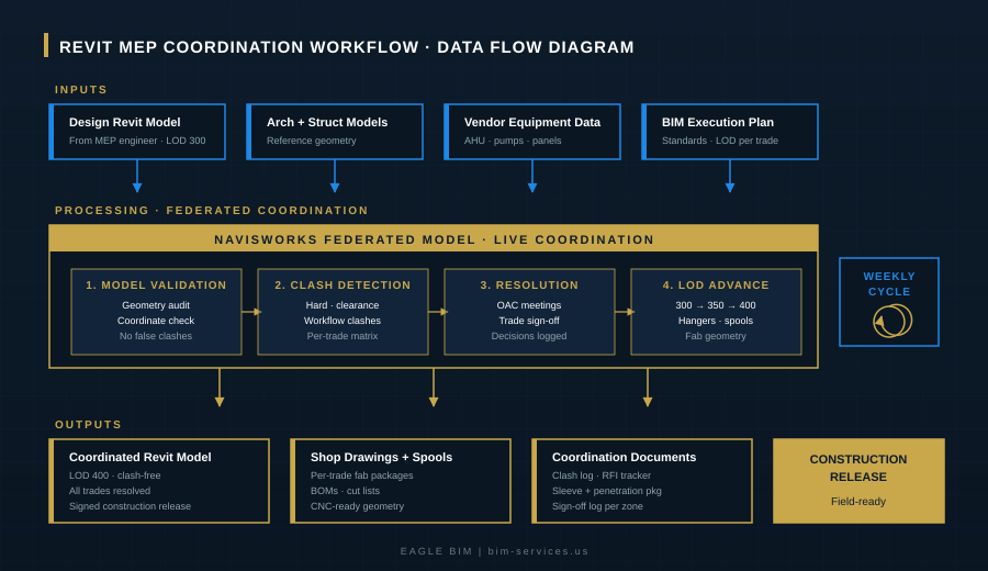
At its core, a Revit MEP coordination workflow takes individual trade models from mechanical, electrical, plumbing, fire protection, and low-voltage engineers, validates each one, federates them with architectural and structural reference geometry, runs systematic clash detection in Navisworks, resolves every conflict through documented OAC meetings, and advances the federated model through LOD 350 to LOD 400 so fabricators can build directly from it. That’s the whole job. The reason it takes eight weeks to do right is that each of those steps has its own technical depth and cannot be compressed past a certain point without breaking the chain.
In 2026, the standard for MEP coordination services on serious commercial projects has moved decisively to LOD 400. Hyperscale data center operators specify it. Tier 1 hospital systems specify it. Semiconductor fab owners specify it. The reason is simple: at LOD 400, the fabricator can build directly from the model without remodeling. At LOD 300, the fabricator effectively has to redo the modeling work themselves, which doubles the labor and creates a gap where rework lives. The Revit MEP coordination workflow that delivers LOD 400 is the workflow contractors are willing to pay for.
The math on a $200 million project illustrates why. If the Navisworks clash detection cadence catches even 5 percent of the conflicts that would otherwise become RFIs during construction, the avoided rework cost can run into the millions. That is the case for spending eight weeks doing coordination properly rather than four weeks doing it poorly. The eight-week framework is built around that math.
Week One: Setup, BEP, and Scope Definition
Week one is not modeling. It is alignment. The Revit MEP coordination workflow starts with a kickoff meeting that confirms the project BIM execution plan (BEP), target LOD per discipline, file exchange protocols, clash tolerances, meeting cadence, and decision rights for unresolved conflicts. Most projects that fail later in coordination fail because this week was skipped.
Specific deliverables for week one: confirmed BEP with all signatures, scope matrix showing which discipline owns which scope at which LOD, file naming and folder structure agreed across all parties, Autodesk Construction Cloud or BIM 360 environment set up with appropriate permissions, and the project coordination schedule baselined against the construction schedule so coordination releases land before fabrication windows. A working BEP and an agreed clash tolerance specification are the two artifacts that matter most. Eagle BIM treats the BEP as a contract document. Without an approved BEP, no model intake.
Most contractors underestimate this week. They want to start clash detection in week one. We resist because clash detection without an approved BEP and validated model files produces false results that consume resolution time without resolving anything. Spending five days getting the foundation right saves three weeks downstream. The discipline of waiting is part of the workflow.
Week Two: Model Intake and Validation
Week two is when actual model files arrive. The Revit MEP coordination workflow requires that every trade model be validated before it enters the federated coordination model. Validation catches geometry errors, coordinate misalignments, broken families, missing system definitions, and anything else that would produce false clashes. Most national MEP BIM services shops skip this step. Eagle BIM does not, because the cost of skipping it is two to three weeks of resolution time chasing clashes that never existed.
What gets checked at this stage: model coordinate alignment against the project shared coordinate system, presence and accuracy of system classifications (so a domestic water pipe is not modeled as a chilled water pipe), workset organization that lets coordination teams isolate trades cleanly, broken or missing families that would create geometry holes, level definitions consistent across trade files, and required parameters for clash filtering. Each trade model gets a validation report sent back to the modeling team if anything fails. Nothing federates until validation passes.
The federated model gets assembled in Navisworks once individual trade models pass validation. This is the single coordination document that lives throughout the rest of the workflow. Architectural and structural reference geometry layer in as fixed references. Each MEP discipline (mechanical, electrical, plumbing, fire protection, low-voltage, specialty systems) layers in as a separately managed workset. The result is a clean baseline coordination model that the rest of the Revit MEP coordination workflow builds on.

Weeks Three and Four: Clash Detection and Resolution Cycle One
Week three is the first real Navisworks clash detection run. Every trade gets clashed against every other trade per a project-specific clash matrix. Hard clashes (physical interference), clearance clashes (insufficient maintenance or operational space), and workflow clashes (sequencing conflicts) all get catalogued separately. Generic Navisworks defaults produce noise. A project-tuned clash matrix produces signal. The Revit MEP coordination workflow depends on this tuning. You can see the deeper detail on how we run clash detection services on a project-specific basis on our services page.
Clash output gets organized by zone, by trade pair, and by priority. A 12-inch duct passing through a structural beam is a higher priority than a 1/2-inch conduit clipping a wall stud. The clash log gets distributed to all trades before the week three coordination meeting so each trade arrives prepared with proposed resolutions. Walking into an OAC meeting with 400 unsorted clashes is how projects waste three hours of expensive trade time. Walking in with the clashes pre-sorted, pre-assigned, and pre-prioritized is how projects resolve 200 clashes in two hours.
Week four is resolution. Each trade owns their assigned clashes and modifies their Revit model accordingly. The federated model gets republished. Resolution decisions get logged in the model with discipline owner, sign-off date, and a brief note on the resolution approach. Reasonable BIM coordination services workflows treat the decision log as a permanent artifact. Without it, the same clash resurfaces six weeks later and nobody remembers what was decided. We have seen this fail on enough projects to know the documentation matters.
By end of week four, the first resolution cycle is complete. The federated model should be substantially clash-free at LOD 300, with a documented decision trail. This is the baseline that the rest of the Revit MEP coordination workflow builds on. If week four ends with 200 unresolved clashes, the project is in trouble. If week four ends with 10 to 20 residual clashes flagged for engineering review, the project is on track.
Week Five: Advance to LOD 350
Week five is the first LOD advance. The model moves from LOD 300 (design coordination) to LOD 350 (trade coordination). What gets added: hangers and supports for every MEP system, sleeves and penetrations through structural elements, connection details where trades interface, and the interfaces between MEP and architectural finishes. MEP BIM services at LOD 350 are what most commercial projects target as their baseline coordinated state. Eagle BIM treats LOD 350 as a way station, not a destination.
Hangers and supports are not decoration. They are real geometry that occupies real plenum space and creates real clashes with other trades. A typical hospital ceiling plenum has hangers from chilled water, domestic water, medical gas, fire protection, electrical conduit, lighting, and cable tray, all competing for the same vertical attachment points to the structural slab. Modeling hangers at LOD 350 is what surfaces those conflicts before they become field RFIs. Skipping hanger modeling is one of the most common failures of cheap BIM coordination services workflows.
Sleeves and penetrations get coordinated with the structural team. Every MEP pass-through gets sized, located, and approved against structural reinforcement requirements. A 24-inch by 24-inch web penetration in a primary girder is not a small ask. It needs structural engineering approval before fabrication. The Revit MEP coordination workflow surfaces these requests systematically so structural has time to engineer and approve them before the steel ships.

| Need MEP Coordination That Actually Delivers LOD 400?
Eagle BIM runs the eight-week Revit MEP coordination workflow on commercial, healthcare, data center, and fab projects across Texas. Real Navisworks clash detection cadence, real OAC discipline, real shop-drawing-ready output. No “contact us for pricing” runaround. |
Week Six: Advance to LOD 400 and Fabrication Geometry
Week six is where the Revit MEP coordination workflow separates itself from generic BIM work. The model advances from LOD 350 to LOD 400 fabrication ready. This means every fitting, every flange, every weld location, every spool break, and every BOM-level component is modeled with manufacturing-grade accuracy. The deliverable is geometry that a fabricator can use directly to drive shop drawings, spool drawings, cut lists, and CNC inputs without remodeling. A serious shop drawing workflow depends entirely on getting this LOD advance right.
On the mechanical side, LOD 400 means ductwork is broken into fabrication spools with actual flanges, slip joints, and connection details modeled. Pipe runs are split at real fitting locations with weld marks and reducer transitions in their actual positions. Equipment is fully detailed including service clearances, vibration isolators, and electrical connection points. On the electrical side, conduit runs are detailed with fittings, junction boxes, and pull point locations. Cable tray includes splice plates, dropouts, and supports. On the plumbing side, pipe is detailed with fittings, valves, hangers, and cleanouts at their actual locations. LOD 400 fabrication geometry at this level of detail is what enables shop drawings to be generated directly from the model rather than recreated from scratch.
This is where the contractor’s investment in Revit MEP coordination workflow pays back. At LOD 400, the fabrication shop builds directly from the model. There is no remodeling step where the fab detailer translates designer intent into manufacturable geometry. The model is the manufacturable geometry. The shop drawing workflow runs straight from the federated coordination model to the shop floor without an intermediate translation step. According to industry guidance from Autodesk on LOD definitions, this is what LOD 400 is for: “the model element is graphically represented within the Model as a specific system, object, or assembly accurate in terms of size, shape, location, quantity, and orientation with detailing, fabrication, assembly, and installation information.” That accuracy is what enables prefab at scale, which is what enables construction schedule compression. LOD 400 fabrication is the technical foundation underneath every successful prefab program in the industry.
Week Seven: Final Clash Detection and Trade Sign-Off
Week seven is the final Navisworks clash detection pass on the LOD 400 federated model. The goal is zero hard clashes, zero clearance clashes outside agreed tolerances, and a fully resolved workflow clash list. Any residual clashes get explicitly documented and signed off by the responsible disciplines with a written justification. The Revit MEP coordination workflow does not permit unresolved clashes to slip silently into the construction release.
Trade sign-off happens at this stage. Each trade lead reviews the federated model, confirms their scope is correctly represented, and signs off on the coordination release for their discipline. This is a formal artifact, not a verbal okay. The sign-off log becomes part of the coordination record and provides the audit trail that owners and operators expect on Tier 1 projects. Without trade sign-off, the MEP coordination services deliverable is incomplete.
Sleeve and penetration drawings get finalized in week seven. These are the documents that go to structural for fabrication and then to the field for verification before pour or steel erection. Every penetration on every floor, every sleeve through every wall, every block-out in every slab. The sleeve drawing package is one of the most underrated deliverables in any Revit MEP coordination workflow because it is what prevents the most expensive single class of field rework: cutting holes in concrete or steel after the fact.
Week Eight: Construction Release and Shop Drawings
Week eight is the release. The coordinated LOD 400 model gets formally issued for construction. Shop drawings get generated from the model and issued per trade. Spool drawings for prefab fabrication get issued to the relevant shops. BOMs and cut lists get generated for material procurement. The clash resolution log, sign-off log, and decision trail get archived as project records. The Revit MEP coordination workflow is complete for this zone of the project. The shop drawing workflow that begins here runs in parallel with the construction sequence and continues until field install closes out.
Practical deliverables in the construction release package: the coordinated federated Revit model and final NWD file with all clashes resolved, coordination drawings organized by zone with sheet sets matching the construction schedule, a sleeve and penetration drawing package, a full clash resolution log with sign-off dates, signed construction release documents for each coordinated zone, and the per-trade shop drawing packages ready for fabrication. Owners and contractors receive the complete coordination record alongside the model itself. This is what BIM coordination services at the LOD 400 level look like when delivered properly.
After week eight, the Revit MEP coordination workflow transitions into construction support mode. Field RFIs come back through the model, change order coordination happens against the released baseline, and the model gets maintained through fabrication and field install. On most Eagle BIM engagements, the same coordination team that ran weeks one through eight continues through construction, ensuring the federated model stays in sync with field reality and that any changes route through the same documented resolution discipline that produced the original release.
Why Eight Weeks, Not Four
The most common pushback from contractors is schedule pressure. Why not run MEP BIM services in four weeks? Why not six? The honest answer is that four weeks does not give the trades enough time to resolve clashes properly between coordination meetings. Six weeks compresses the LOD 350 to LOD 400 advancement into a window that produces sloppy fabrication geometry. Eight weeks gives the workflow room to breathe.
The compressed timelines tend to produce a coordinated model that looks clean on screen but fails when fabrication starts. A 12-inch chilled water main looks like a 12-inch chilled water main in the model whether the spool segmentation is correct or not. The difference shows up at the fab shop when the shop drawing produces a spool that does not match the field reality. Eight weeks of disciplined Revit MEP coordination workflow produces spools that match. Four weeks of compressed coordination produces RFIs.
Some projects warrant compression. Small commercial scope at LOD 300 can run in four to five weeks. Large healthcare or data center scope at LOD 400 sometimes takes ten to twelve weeks. The eight-week framework is the typical standard for mid-sized commercial projects requiring LOD 350 baseline with LOD 400 advancement on mission-critical zones. Eagle BIM adapts the framework to the project. The discipline of the workflow stays constant. The duration scales.
If you want a deeper view of what LOD 400 actually delivers at the fabrication level, the Autodesk LOD reference is the authoritative source. The LOD definitions there match what Eagle BIM delivers on every Revit MEP coordination workflow engagement, and the eight-week framework is built to deliver against those definitions consistently.
How Eagle BIM Runs the Workflow
Eagle BIM is based in Texas, in association with BIMPRO LLC out of Pflugerville. We run the eight-week Revit MEP coordination workflow on commercial, healthcare, data center, semiconductor fab, multifamily, and industrial projects across Texas and beyond. Our standard delivery is LOD 350 on commercial work and LOD 400 on mission-critical builds, with Navisworks clash detection cycles running weekly through construction release.
Our team works natively in Autodesk Revit and Navisworks, publishes coordination models through Autodesk Construction Cloud and BIM 360, and supports Procore for RFI and submittal workflows. We deliver coordinated federated models, full clash resolution logs, sleeve and penetration drawing packages, signed construction release documents per zone, and the per-trade shop drawing packages that fabrication shops need to build directly from the model. Every coordination decision is logged with discipline owner and sign-off date. This is the kind of audit trail Tier 1 owners and contractors expect on serious projects. Our shop drawing workflow runs from the same federated model that drives the LOD 400 fabrication geometry, so the drawings and the model never go out of sync.
Our MEP coordination services scope is broken out by discipline rather than bundled. Mechanical, electrical, plumbing, fire protection, low-voltage, and specialty systems each have their own clash matrix and resolution log. This is how serious MEP BIM services get scoped in 2026. Bundling everything as “MEP” produces vague deliverables and vague pricing. Discipline-level scoping produces clear deliverables and predictable timelines.
What to Ask Before Hiring a BIM Partner
If you are evaluating BIM coordination services partners for an upcoming project, here are the questions worth asking. Do you have a documented Revit MEP coordination workflow I can review before we sign? Most firms will say yes and then deliver a generic flowchart. The good ones can show you week-by-week deliverables, sample clash matrices, and actual sign-off logs from previous projects.
What is your typical LOD on commercial work? What is your typical LOD on data center or healthcare work? The honest answer is LOD 350 for one and LOD 400 for the other. Firms that say LOD 400 on everything are either overpromising or padding fees. Firms that say LOD 300 on everything are leaving fabricators to remodel from scratch. The serious firms scope LOD per project type and explain why.
How often do you run Navisworks clash detection? Weekly is the standard on serious projects. Anything less frequent than that and clashes accumulate faster than they can be resolved. How do you document coordination decisions? The decision log should be a model artifact, not a separate Excel file that nobody updates. How do you handle vendor model integration? Vendor equipment models arrive throughout the project and have to integrate cleanly into the federated model without breaking the coordination work already done.
The firms that have clear answers to these questions are the ones worth working with. The ones who pivot to talking about “flexible engagement models” or “rapid turnaround” are the ones to be careful with. A serious Revit MEP coordination workflow has structure, has documentation, and has predictable deliverables. Anything less than that is not coordination. It is just modeling that happens to be billed at coordination rates.
The Bottom Line on Revit MEP Coordination
The construction industry has changed. MEP coordination services and Navisworks clash detection are no longer back-office BIM functions. They are the workflows that determine whether a project hits its schedule and whether the fabrication shop builds directly from the model or has to remodel from scratch. The contractors who win on schedule in 2026 are the ones running disciplined Revit MEP coordination workflow to LOD 400 with documented sign-off trails. The ones who do not are paying for it in RFIs and rework. A clean shop drawing workflow rooted in LOD 400 fabrication geometry is what separates the projects that finish on schedule from the ones that do not.
Eagle BIM’s eight-week framework is one approach to running the Revit MEP coordination workflow properly. It is not the only valid approach. There are firms that run six-week workflows successfully on smaller projects and firms that run twelve-week workflows on larger ones. What matters is that the framework is documented, the deliverables are defined, the sign-off discipline is enforced, and the LOD advances are deliberate. Without those four elements, the workflow is just expensive modeling.
Whether you choose Eagle BIM or another firm, choose a partner who can show you the framework in writing, who scopes by discipline rather than bundling, who runs Navisworks clash detection on a published cadence, and who delivers a documented sign-off trail with the model. That is what serious BIM coordination services look like in 2026. Anything less is not serious.
| Talk to Eagle BIM About Your Next Project
Send us your project scope and we will come back with a proposal that maps the eight-week Revit MEP coordination workflow against your construction schedule. Real deliverables, real timelines, real LOD targets per discipline. No “contact us for pricing” runaround. |