Roughly half of the construction spend in the United States goes into existing buildings. Renovations, retrofits, adaptive reuse, tenant fit-outs, medical and lab upgrades, facility modernisations. And almost every one of those projects starts with the same problem: the existing drawings are wrong. They are old, they were never as-built, the building has been modified a dozen times, the MEP has been rerouted twice, and a wall that should be where the plan shows it is actually three inches to the left and out of plumb. This is exactly the gap that Scan to BIM services are designed to close.
This is the problem Scan to BIM services solves. By capturing the building exactly as it stands today with a 3D laser scanner and then converting that point cloud into a parametric Revit model, the design team gets an as-built that is actually accurate. No more measuring tape errors, no more design surprises, no more change orders because the riser was assumed to be in a different bay.
This article covers the full picture: what Scan to BIM services actually means, how the scan to BIM process works from field capture to final Revit handoff, what a point cloud is and how it is captured, the difference between LOA (Level of Accuracy) and LOD (Level of Development), what software the industry uses, what gets delivered, how accurate it actually is, and the four core use cases where scan to BIM pays for itself many times over. We will close with the questions clients ask Eagle BIM most often.
Two related Eagle BIM articles set useful context: Scan-to-BIM Healthcare Renovation covers a specific high-value use case in detail, and BIM Level of Development (LOD) explains how LOD fits alongside LOA in the deliverable spec. This article focuses on Scan to BIM services as the discipline.
Scan to BIM · What It Actually Means
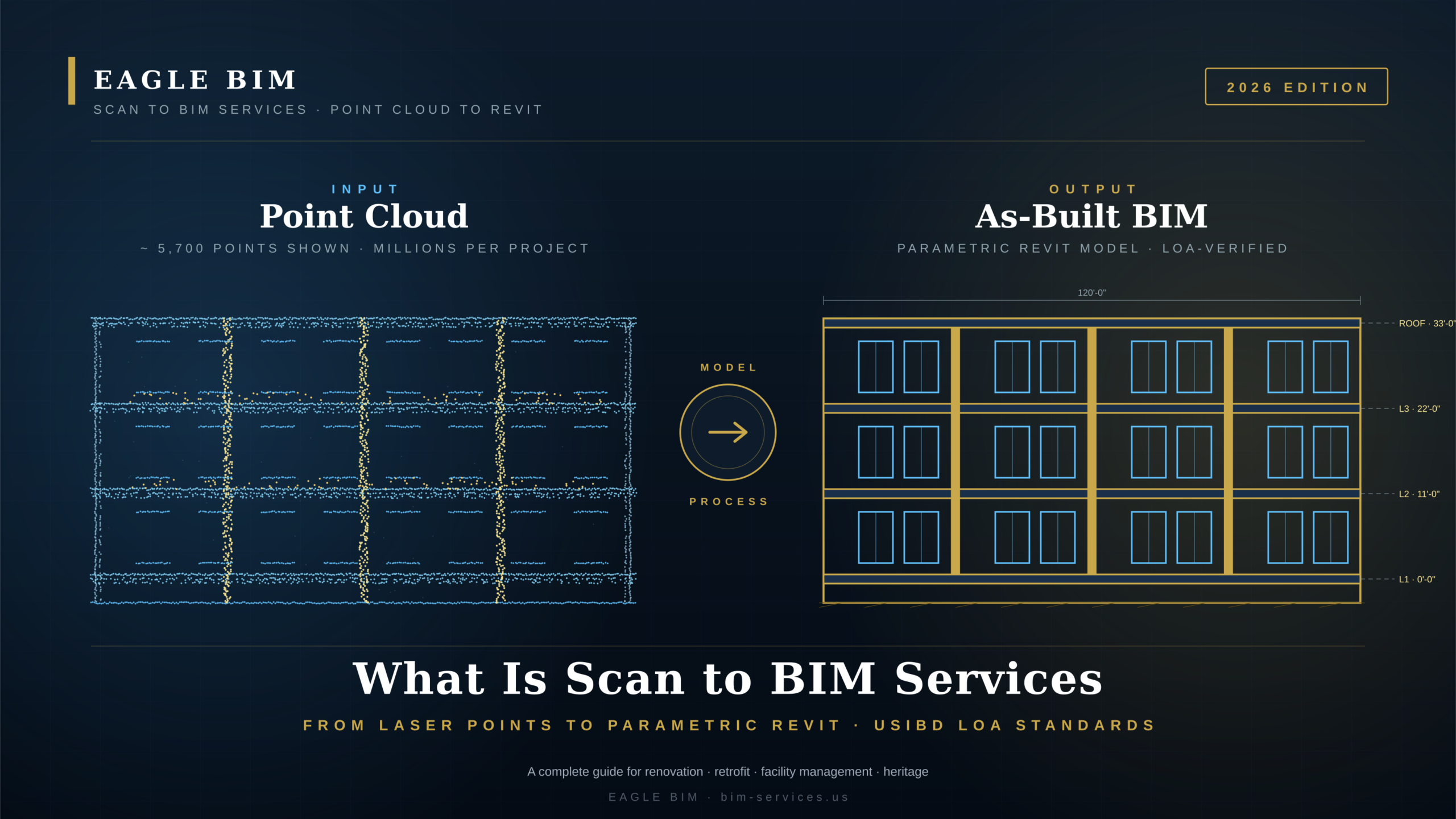
| Scan to BIM services is the process of capturing an existing building with a 3D laser scanner, producing a point cloud of millions of measured points, and converting that point cloud into a parametric Revit model. The output is an as-built BIM model that reflects the building as it stands today, accurate to within a few millimeters depending on the specified LOA (Level of Accuracy). |
Scan to BIM services sits at the intersection of three disciplines: surveying, photogrammetry, and BIM authoring. A surveyor or BIM technician sets up a terrestrial laser scanner at multiple positions inside and around a building. At each position the scanner spins, fires laser pulses at every surface in view, measures the return time, and records millions of XYZ coordinates per setup. Those measurements stitch together into a single coordinated point cloud that describes the building geometry with high precision. This is the input stage of every Scan to BIM services engagement.
The point cloud by itself is not useful for design. It is just dots in space · there is no concept of ‘wall’ or ‘door’ or ‘pipe’ inside it. The second half of Scan to BIM services is the modeling step. A BIM technician brings the point cloud into Revit, sets up a shared coordinate system, and traces parametric Revit families (walls, slabs, doors, ducts, pipes) directly off the point cloud geometry. The result is a model that behaves like any other Revit model · schedulable, taggable, dimensionable, coordination-ready · but that reflects the actual as-built condition rather than someone’s interpretation of old drawings. This is what production Scan to BIM services actually deliver.
The terminology overlaps in confusing ways. Point cloud to BIM, point cloud to Revit, laser scan to BIM, and as-built BIM modeling all describe pieces of the same workflow. Different vendors emphasize different terms. Eagle BIM uses Scan to BIM services as the umbrella term covering field scanning (when engaged for it), registration, point cloud processing, modeling, QC, and delivery · the full pipeline from physical building to usable Revit file.
A common misconception is that Scan to BIM services produce an automatic model. They do not. Modern software has improved feature detection and there are emerging tools that can extract walls, ceilings, and obvious geometry automatically, but for production-grade BIM deliverables the bulk of the modeling is still done by trained technicians tracing off the point cloud. Automation is improving steadily, but every project still needs a human to make decisions about which elements get modeled, how they get classified, and what level of detail each element needs.
Scan to BIM Services Process · From Field Capture to Final Revit Model
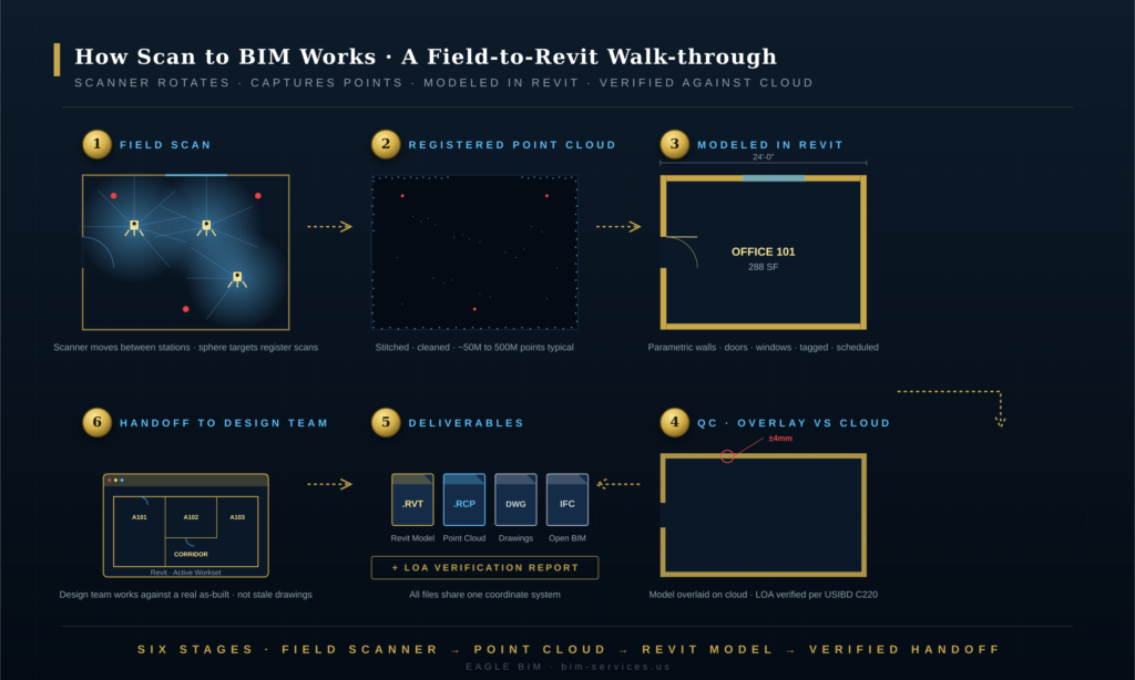
| The scan to BIM process runs through six stages: plan and scope, field capture, registration and cleaning, import to Revit, trace and model, then QC and delivery. Scan and registration take 3 to 8 days on a typical project. Modeling takes 2 to 6 weeks depending on building size and target LOA. The full Scan to BIM services engagement is usually a 4 to 8 week pipeline. |
The scan to BIM process looks similar on every project · six repeatable stages · but each stage has decisions that drive cost, schedule, and final model quality. Eagle BIM uses the same Scan to BIM services workflow on a 5,000 SF medical office and on a 500,000 SF commercial tower; what changes is the scan station count, the modeling effort, and the QC cycle length.
Stage 1 · Plan and Scope. The most-skipped stage and the most expensive when it goes wrong. The team defines what gets modeled (architectural shell only? MEP? furniture? landscape?), at what LOA target, in what software, against what coordinate system, and at what level of detail. The scope document drives every downstream decision in the Scan to BIM services engagement. A well-scoped project takes half the time of a poorly-scoped one because nothing has to be redone.
Stage 2 · Field Capture. A scanning crew sets up the laser scanner at every required station · typically every 20 to 40 feet inside a building, every 60 to 100 feet outside, with overlap. Each station takes 3 to 8 minutes depending on resolution. Target spheres or checkerboard targets are placed in overlap zones to help with registration later. Most Scan to BIM services projects can be scanned in 1 to 3 days; larger or more complex sites can take longer.
Stage 3 · Registration and Cleaning. Each scan position produces its own coordinate system. Registration is the process of stitching all those individual scans together into a single unified point cloud. Software (Leica Cyclone, FARO SCENE, Trimble RealWorks, Autodesk ReCap) automatically detects shared targets and registers scans · a trained technician verifies and adjusts. After registration, the cloud is cleaned of noise, scan artifacts, people, vehicles, and other transients. A clean registered cloud is the foundation for everything that follows in Scan to BIM services work.
Stage 4 · Import to Revit. The clean point cloud (typically in .RCP format from Autodesk ReCap) is brought into Revit as a reference object. The technician sets up shared coordinates, project north, and a project base point that aligns with the building survey. Levels are pulled directly from the cloud. From this point on, every wall, door, and pipe that gets modeled is referenced against the actual measured geometry · the heart of how Scan to BIM services create value.
Stage 5 · Trace and Model. The longest stage. A BIM technician (or team) places parametric Revit families · walls, floors, ceilings, doors, windows, columns, MEP equipment · using the point cloud as the underlay. This is the stage where the Scan to BIM services engagement creates most of its value: turning raw geometry into intelligent BIM data. Modeling pace depends on the target LOA and the complexity of the building.
Stage 6 · QC and Delivery. The final stage overlays the completed BIM model against the point cloud and checks every element against the LOA tolerance. Deviations outside tolerance are flagged and corrected. A formal LOA verification report is produced. The model is then packaged for delivery · typically a Revit file, an exported IFC, a set of base drawings, and the cleaned point cloud. The Scan to BIM services engagement closes when the client signs off on the LOA verification.
What Is a Point Cloud and How Is It Captured
| A point cloud is a dataset of millions of XYZ coordinates that together describe the 3D geometry of a physical space. Each point also carries color and intensity values. Point clouds are captured by terrestrial laser scanners (FARO, Leica, Trimble), mobile/SLAM scanners (NavVis, Leica BLK2GO), drones (for facades and large sites), and increasingly by LiDAR-equipped iPhones and iPads for smaller spaces. |
A point cloud is, mechanically, just a long list of numbers. Each row contains an X coordinate, a Y coordinate, a Z coordinate, an intensity value (how strongly the laser pulse returned), and usually an RGB color value (sampled by the scanner’s onboard camera). A small office might produce a 50-million-point cloud. A large hospital might produce 500 million points or more. Modern cloud-storage formats (.RCP, .E57, .PTS, .LAS) compress these efficiently, but the data volume is still significant · typical project clouds run 5 to 50 GB. Every Scan to BIM services engagement starts with managing this raw data.
Several capture technologies feed into Scan to BIM services today, and the right choice depends on the building, the schedule, and the target LOA:
Terrestrial Laser Scanners (TLS). The workhorses of Scan to BIM services. FARO Focus, Leica RTC360, Trimble X7, Z+F Imager. These sit on a tripod, spin 360°, and capture millions of points per setup. Accuracy is in the range of ±2 to ±5 mm at typical building distances. They are the default for production-grade as-built work targeting LOA 20 to LOA 40.
Mobile / SLAM scanners. NavVis VLX, Leica BLK2GO, GeoSLAM. A technician walks through the space carrying the scanner, which builds up the point cloud using Simultaneous Localization and Mapping. Much faster than tripod scanning but with lower accuracy (typically ±10 to ±25 mm). Excellent for large building inventories, facility management LOA 20 work, and high-throughput projects.
Drone photogrammetry and LiDAR. For exterior facades, roofs, large industrial sites, and inaccessible areas. Drones equipped with LiDAR sensors or high-resolution cameras (for photogrammetry) produce point clouds of building exteriors and surrounding terrain. Used as a complement to terrestrial scanning rather than a replacement for interior work.
iPhone / iPad LiDAR. The cheapest entry point. Apps like 3D Scanner App, Polycam, or Canvas turn a LiDAR-equipped iPhone or iPad into a basic scanner. Accuracy is in the range of ±20 to ±50 mm depending on conditions. Not suitable for production Scan to BIM services targeting LOA 30 or better, but useful for quick documentation, small-room captures, and field verification.
Selecting the right capture technology is part of the planning stage. Eagle BIM’s Scan to BIM services engagement starts with a conversation about what the final BIM model will be used for · that drives the LOA target, which drives the scanner choice. A facility management model at LOA 20 might be captured with SLAM in a single day; a heritage documentation project at LOA 40 needs terrestrial laser scanning with extended station times and tighter target control.
LOA (Level of Accuracy) vs LOD (Level of Development)
| LOA (Level of Accuracy) describes how closely the BIM model matches the physical building, measured as a tolerance band per the USIBD specification C220. LOD (Level of Development) describes the geometric and informational detail in a BIM element, per BIMForum USA. LOA and LOD are independent · a model can be high-LOA but low-LOD or vice versa. As-built scan to BIM deliverables typically target LOA 20 to LOA 30. |
Few terms in scan-to-BIM cause more confusion than LOA and LOD. They sound similar, they get used interchangeably in casual conversation, and they are completely different things. Eagle BIM clients hiring Scan to BIM services regularly ask for ‘LOD 300 scan to BIM’ when they actually need ‘LOA 30 with LOD 300 geometry’ · and the difference matters. Every Scan to BIM services scope of work should specify both.
LOD · Level of Development · is defined by the BIMForum USA LOD Specification. It describes how richly developed a BIM element is, in geometry and embedded information. An LOD 200 wall is generic (size and location). An LOD 300 wall has specific dimensions, family type, and manufacturer attributes. An LOD 400 wall includes fabrication-level detail. LOD is about the BIM element itself, not about how it relates to the physical building.
LOA · Level of Accuracy · is defined by the USIBD specification C220 (the Level of Accuracy Specification Guide published by the U.S. Institute of Building Documentation). It describes how closely the BIM model matches the as-built reality, as a tolerance. LOA 20 means ±15 mm. LOA 30 means ±6 mm. LOA 40 means ±3 mm. LOA is about the relationship between the digital model and the physical building.
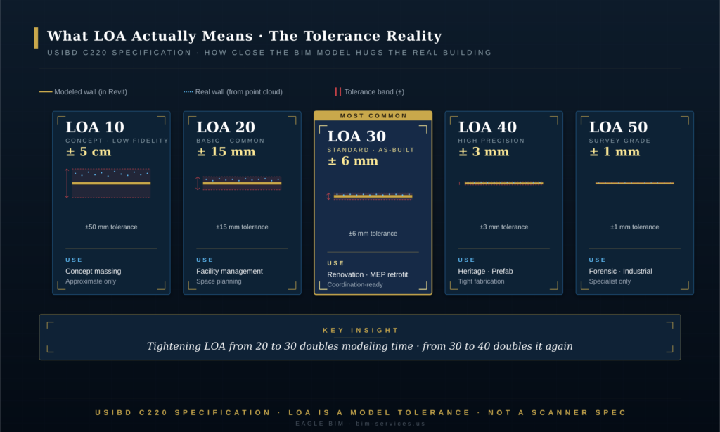
In practice, Scan to BIM services deliverables target LOA 20 to LOA 30 for the vast majority of projects. LOA 20 (±15 mm) is sufficient for facility management, space planning, and most renovation backgrounds. LOA 30 (±6 mm) is the workhorse for design-development renovation, MEP retrofit coordination, and most architectural as-builts. LOA 40 (±3 mm) shows up on heritage projects, MEP fabrication tie-ins, and prefab interface zones where field tolerances are tight.
LOA 10 and LOA 50 are edge cases. LOA 10 (±50 mm or worse) is concept-stage, not really ‘accurate’ in any meaningful sense and rarely a target for paid Scan to BIM services. LOA 50 (±1 mm) is forensic-level work for structural deflection studies, industrial alignment, or specialist scope · rarely applied to a whole building.
The right LOA target depends entirely on what the model will be used for. Over-specifying LOA drives cost up disproportionately · LOA 40 work takes roughly 2 to 3 times the modeling effort of LOA 20 because the scanning, registration, and modeling tolerances all tighten together. Under-specifying LOA produces a deliverable that the design team cannot trust. The first conversation Eagle BIM has with a new Scan to BIM services client is almost always about matching the LOA target to the actual downstream use case.
For the LOD side of the conversation, see our companion article on BIM Level of Development. The two specifications · USIBD C220 for LOA and BIMForum USA for LOD · should both appear in any complete Scan to BIM services scope of work.
Scan to BIM Software · Revit, ReCap, FARO, Cyclone
| The standard Scan to BIM services software stack is: Autodesk ReCap or Leica Cyclone for point cloud processing, FARO SCENE or Trimble RealWorks for registration depending on scanner brand, and Autodesk Revit for the point cloud to Revit modeling step. Navisworks handles federation and clash checking against the as-built. Each tool covers a specific stage of the pipeline. |
The Scan to BIM services software ecosystem is more fragmented than other parts of the BIM world because each stage of the workflow has its own specialised tools. A typical pipeline uses three to five different applications. Eagle BIM works across all of them and picks the right combination for each project.
Scanner manufacturer software (FARO SCENE, Leica Cyclone REGISTER, Trimble RealWorks, Z+F LaserControl). Each major scanner brand ships its own registration and processing software. They are optimized for that brand’s scanners but most can import other formats too. SCENE and Cyclone are the most common in commercial AEC Scan to BIM services practice.
Autodesk ReCap Pro. The bridge between scanner software and Revit. ReCap imports registered point clouds, lets the technician clean and decimate them, and exports the .RCP format that Revit reads natively. Most Scan to BIM services engagements pass through ReCap at some point even when registration was done elsewhere. For Eagle BIM, ReCap is the standard handoff format from scanning crews to the Scan to BIM services modeling team.
Autodesk Revit. The modeling tool at the heart of Scan to BIM services. Once the .RCP point cloud is linked into Revit, the technician traces walls, doors, slabs, MEP, and other elements directly off the cloud. Revit has native point cloud snapping, which speeds up the trace work considerably. The point cloud to Revit step happens almost entirely inside Revit.
Autodesk Navisworks. Used for federating the completed as-built Revit model with new design models and running clash detection. This is where the Scan to BIM services deliverable transitions into the coordination workflow, and the point where downstream design teams start consuming the as-built model produced by Scan to BIM services.
Specialty tools. Some projects benefit from specialised software · CloudCompare for advanced point cloud analysis, Pix4D for drone photogrammetry processing, As-Built for Revit by FARO for plug-in modeling assistance, ClearEdge3D EdgeWise for partial automation of pipe and wall detection. Eagle BIM uses these as needed but does not require clients to standardize on them.
There is a growing category of AI-assisted modeling tools that promise to automate parts of the point cloud to BIM workflow. Tools like ClearEdge3D, PointFuse, and the AI features in newer ReCap versions can detect walls, ceilings, pipes, and conduit automatically. The current state of the art handles maybe 50 to 70 percent of basic geometric features on a clean cloud. The remaining 30 to 50 percent · including all the classification, family selection, parametric properties, and edge cases · still needs human modeling. AI is changing the economics of Scan to BIM services but it is not yet replacing the modeler.
Scan to BIM Services · Typical Deliverables
| A complete Scan to BIM services deliverable package includes: the cleaned registered point cloud (.RCP or .E57), the as-built Revit model (.RVT), exported drawings (floor plans, RCPs, sections, elevations), an LOA verification report per USIBD specification C220, an IFC export for non-Revit users, and the project coordinate transformation file. All deliverables share the same coordinate system. |
Not every Scan to BIM services engagement produces the same outputs, and the variation matters. The Scan to BIM services deliverable package should be specified in the scope of work and verified before sign-off. Eagle BIM’s standard deliverable package, refined across many commercial and healthcare projects, includes the following items.
Registered point cloud (.RCP / .E57). The cleaned, registered cloud is itself a Scan to BIM services deliverable. The client receives it because they may want to verify the model later, archive the as-built condition, or use the cloud directly in other workflows. .RCP is the Autodesk-native format that Revit reads; .E57 is the open ASTM E57 standard for point cloud interoperability across software platforms.
As-built Revit model (.RVT). The core Scan to BIM services deliverable. A parametric Revit model with all in-scope elements modeled to the specified LOA and LOD. The model is organized with proper workset structure, project information, shared parameters, and family library appropriate for downstream design use.
Exported drawings. Floor plans, reflected ceiling plans, building sections, elevations, and (when in scope) MEP routing plans. These are produced from the Revit model and delivered as PDF and as CAD (DWG) exports. The drawings are tagged with as-built dimensions pulled directly from the as-built BIM modeling.
LOA verification report. A formal document that overlays the completed Revit model against the source point cloud and reports deviation statistics per the USIBD specification C220 methodology. The report typically includes summary statistics, a histogram of deviations, callouts on any elements that fall outside the target LOA tolerance, and a sign-off block. This is the document that closes a Scan to BIM services engagement.
IFC export. An open-format export for clients or downstream design teams that do not use Revit. IFC 2×3 or IFC 4 depending on client preference. Useful for project teams running ArchiCAD, AECOsim, or platform-agnostic coordination tools.
Coordinate transformation file. A small but critical deliverable. The transformation matrix that aligns the project coordinate system used in the Scan to BIM services deliverable with the client’s survey datum, site plan, or campus master coordinate system. Without this file, the model cannot be confidently integrated with site-scale or campus-scale work later.
Optional deliverables that come up on specific projects include orthophoto images generated from the point cloud (useful for facade documentation), 360° panoramic captures from each scan station (used for virtual walkthroughs and asset documentation), and CSV exports of asset registers for facility management integration.
| Want a scan-to-BIM deliverable that holds up to LOA verification?
Eagle BIM delivers Scan to BIM services for healthcare renovations, multifamily retrofits, commercial fit-outs, data centers, and heritage projects. Every engagement includes the LOA verification report and full deliverable package described above. |
How Accurate Is Scan to BIM · The 5 mm to 15 mm Tolerance Reality
| Production Scan to BIM services deliverables typically land between ±6 mm and ±15 mm (LOA 30 to LOA 20) on as-built dimensions. Survey-grade work (LOA 40, ±3 mm) is achievable but costs roughly twice as much in modeling effort. The accuracy floor is set by the scanner (typically ±2 mm), but the practical accuracy is set by the LOA the modeling team agrees to hold. |
Accuracy is the question every client asks first, and the answer has more nuance than the single-number response. The accuracy of a Scan to BIM services deliverable is the product of four contributing tolerances · scanner accuracy, registration accuracy, modeling tolerance, and the geometric simplification inherent in tracing curved or irregular surfaces as parametric families. The final LOA on any Scan to BIM services project is the cumulative sum.
Scanner accuracy. Modern terrestrial laser scanners measure individual points to ±2 to ±5 mm at typical building distances. That is the floor. SLAM mobile scanners are looser, typically ±10 to ±25 mm. iPhone LiDAR is looser still. The scanner accuracy is the only thing the modeling team cannot improve · once the point is measured, it is what it is.
Registration accuracy. Stitching multiple scan setups into a single cloud adds error. Good registration with proper target control adds 1 to 3 mm of accumulated error across a building. Poor registration (insufficient targets, weak loop closure, daisy-chained setups) can add 10 to 20 mm or worse. A skilled crew with proper QC keeps registration error to a minimum.
Modeling tolerance. This is the LOA being held by the modeling team. A technician modeling at LOA 30 will trace walls to within ±6 mm of the point cloud. A technician modeling at LOA 20 will trace to within ±15 mm. The choice of LOA controls how much time the modeler spends fine-tuning each element. Tightening LOA from 20 to 30 roughly doubles the modeling time per element.
Geometric simplification. Real buildings have curves, sags, bulges, and irregularities that do not map cleanly to parametric Revit families. A wall that is half an inch out of plumb at the top has to be modeled as either plumb (introducing some error) or as a tilted wall (more model complexity). Every Scan to BIM services project makes hundreds of these small simplification decisions, and they add small amounts of error to the deliverable.
All of which is why the realistic accuracy range for production Scan to BIM services work is ±6 mm to ±15 mm · LOA 30 to LOA 20. That covers the majority of design-development, renovation, retrofit, and facility management use cases. Tighter LOA is achievable but each step tighter roughly doubles the cost. The conversation with the client should always start with the question: what is the model being used for, and what tolerance does that downstream use case actually require?
Scan to BIM Use Cases · Renovation, Retrofit, Facility Management, Heritage
| Scan to BIM services pays off in four primary use cases: existing-building renovation (the largest market by spend), MEP and structural retrofit, facility management and asset registers, and heritage documentation for preservation and adaptive reuse. Each use case has its own typical LOA target and modeling depth. |
The four use cases differ in what they need from the BIM model and therefore in how the Scan to BIM services engagement is scoped. Understanding which use case drives a specific project is the single most important input to the scope of work.
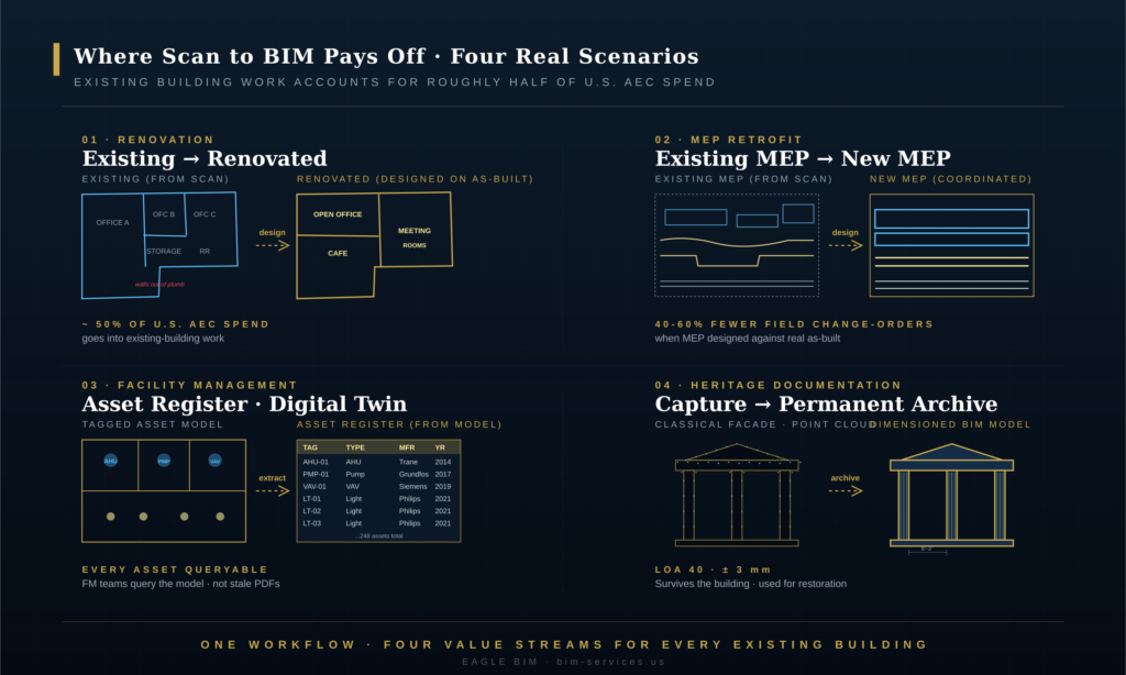
Renovation and Adaptive Reuse. The largest category by project count and probably by total spend. Office-to-residential conversions, hospitality fit-outs, retail remodels, school upgrades. The Scan to BIM services deliverable provides the design team with an accurate as-built to design against · walls that are actually plumb on the drawing, slabs that match the field condition, MEP routes that are where they really are. Most renovation Scan to BIM services engagements target LOA 20 to LOA 30.
MEP and Structural Retrofit. HVAC replacement, electrical service upgrades, sprinkler system additions, structural reinforcement, lab equipment migrations. The retrofit design team needs to know where every existing pipe, duct, beam, and conduit actually runs so they can design around it. Scan to BIM services delivers the as-built MEP and structure in a coordinated Revit model that drops directly into the design workflow. Typical LOA target: LOA 30.
Facility Management. Asset registers, space utilization tracking, equipment maintenance routing, energy modeling, lease administration. The FM use case usually needs less geometric precision but more attribute data · every door, fixture, and piece of equipment tagged with maintenance information, manufacturer data, and lifecycle attributes. Scan to BIM services for FM often comes in at LOA 20 (the geometry just needs to be good enough to find things) but with rich element metadata.
Heritage Documentation. Historic preservation, irreplaceable cultural assets, adaptive reuse of designated structures. The model is being used for both immediate design work (often restoration) and as a long-term digital archive. Scan to BIM services for heritage typically target LOA 40 because the geometric detail of original ornament, irregular construction, and historical character has to survive in the model. The Scan to BIM services output for heritage is also often produced as both a Revit model and a high-fidelity orthophoto archive.
A handful of other use cases come up regularly: forensic engineering (structural deflection studies, post-incident documentation), industrial alignment (process equipment, conveyor systems), and commercial real estate due diligence (high-precision area certification, lease audit support). Each has its own LOA profile but follows the same six-stage scan to BIM process.
For a deeper look at one of these use cases, see our companion article Scan-to-BIM Healthcare Renovation. Healthcare is one of the most demanding use cases · tight tolerances, dense MEP, active patient areas, and strict regulatory documentation requirements. Many of the lessons there transfer to other complex renovation work.
How Eagle BIM Delivers Scan to BIM Services
| Eagle BIM delivers Scan to BIM services as an integrated engagement: scope and LOA definition, scan crew coordination (or import of client-provided scans), registration and cleaning, point cloud to Revit modeling, formal LOA verification per USIBD specification C220, and full deliverable package. Engagements run 4 to 8 weeks depending on size and target LOA. |
Eagle BIM, in association with BIMPRO LLC, runs Scan to BIM services from our Pflugerville, Texas office for commercial, healthcare, multifamily, data center, semiconductor fab, and heritage projects across Texas and the broader United States. We accept client-supplied point clouds (often from a survey partner or in-house team) and we also coordinate full field-scanning crews when the client needs a turnkey Scan to BIM services engagement.
The standard Eagle BIM Scan to BIM services engagement covers the six-stage workflow described earlier. We come in at the planning stage, work with the client to write the scope document and define the LOA target, coordinate or perform the field scanning, run registration and cleaning, model in Revit, and close with formal LOA verification. The deliverable package is consistent across project types · what changes is the scope, the LOA target, and the element-level detail.
Our software stack is flexible: Autodesk ReCap for cloud processing, Leica Cyclone or FARO SCENE for registration depending on scanner brand, Revit for the as-built BIM modeling, Navisworks for federation when the as-built model gets handed off to coordination. Clients on ArchiCAD or other platforms get IFC exports rather than .RVT files. Most of our work passes through Revit because that is where the downstream design team usually lives.
Geographically we are based in Texas and active across Houston, Dallas-Fort Worth, Austin, San Antonio, and various sites across the broader USA. The Scan to BIM services workflow does not change with location · what changes is local context, scheduling, and the building stock typical to each market. Texas has a heavy load of healthcare expansion, semiconductor fab construction, and multifamily retrofit work right now; all three need Scan to BIM services as the front end of design.
If you want to see how Scan to BIM services fits into the wider Eagle BIM service mix, our Scan to BIM Services page covers it. For Houston-specific work · including the Texas Medical Center campus · see our Houston BIM Coordination Services landing page. Architectural as-built work also intersects our Architectural BIM Services scope.
| Have an existing building you need scanned and modeled?
Send Eagle BIM the basics · square footage, target LOA, intended downstream use case · and we will scope a Scan to BIM services engagement against your schedule. We accept client-supplied point clouds or coordinate full field-scanning crews. |
Frequently Asked Questions
These are the questions Eagle BIM hears most often from clients evaluating Scan to BIM services for the first time. The answers are short and direct.
How accurate is scan to BIM?
Production Scan to BIM services deliverables typically land between ±6 mm and ±15 mm · LOA 30 to LOA 20 per the USIBD C220 specification. Tighter accuracy (LOA 40, ±3 mm) is achievable but roughly doubles the modeling cost. The right Scan to BIM services accuracy depends on what the model will be used for · facility management is fine at LOA 20, MEP retrofit needs LOA 30, heritage and prefab need LOA 40.
How long does scan to BIM take?
Field scanning takes 1 to 3 days on a typical project. Registration and cleaning takes 2 to 5 days. Modeling takes 2 to 6 weeks depending on building size, target LOA, and element scope. A full Scan to BIM services engagement on a mid-size commercial building (50,000 to 200,000 SF) usually runs 4 to 8 weeks from kickoff to delivery.
What is the difference between LOA and LOD?
LOA (Level of Accuracy, per USIBD C220) describes how closely the model matches the physical building, measured as a tolerance. LOD (Level of Development, per BIMForum USA) describes how detailed the BIM element is in geometry and embedded data. A model can be high-LOA but low-LOD (the geometry matches reality closely but the elements are generic) or vice versa. A complete Scan to BIM services scope specifies both LOA and LOD targets, because both control different aspects of the Scan to BIM services deliverable.
Do you need to scan the whole building?
No. Scope can be limited to specific areas, floors, or trade zones. Many Scan to BIM services engagements target only the renovation footprint plus a buffer for coordination with adjacent work. Eagle BIM works with clients to scope the scan to the area where the as-built model adds value, which controls cost.
Can you work from a point cloud my surveyor already captured?
Yes. Eagle BIM accepts client-supplied point clouds in any common format · .RCP, .E57, .PTS, .LAS. We run a brief QA on the supplied cloud to confirm registration quality, target control, and coverage gaps. If the cloud is usable, we proceed directly to modeling. If there are issues, we flag them up front and either request supplementary captures or proceed with documented limitations.
What does scan to BIM cost?
Cost for Scan to BIM services depends on building size, target LOA, element scope, and whether field scanning is included. The two main drivers are square footage (which sets scanning effort) and LOA target (which sets modeling effort). Eagle BIM produces a project-specific scope and fee for every Scan to BIM services engagement after a brief discovery call. We do not publish flat per-square-foot pricing because the variation across project types is too large to be meaningful as a single number.
Can scan to BIM be automated?
Partially. Modern point cloud to BIM tools can detect walls, ceilings, floors, and some MEP features automatically. The current state of the art handles roughly 50 to 70 percent of basic geometric features on a clean point cloud. The remaining 30 to 50 percent · element classification, family selection, parametric properties, edge cases, irregular geometry · still needs a human modeler. AI is changing the economics of Scan to BIM services steadily but is not yet replacing the modeler.
What software do I receive the model in?
By default, the Scan to BIM services deliverable is an Autodesk Revit file (.RVT) for the current or recent Revit version. Clients on other platforms receive an IFC export (IFC 2×3 or IFC 4) plus the point cloud and drawings. The Revit file is the most common format because that is where most U.S. AEC downstream design work happens.